3-27
CHASSIS
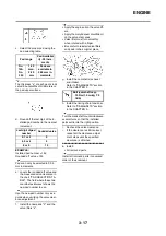
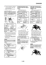
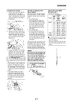
4. Adjust:
• Steering ring nut
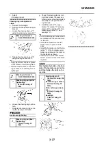
Steering ring nut adjustment
steps:
a. Remove the headlight.
b. Remove the handlebar and upper
bracket.
c. Loosen the steering ring nut "1"
using the steering nut wrench "2".
d. Tighten the steering ring nut "3"
using steering nut wrench "4".
• Apply the lithium soap base grease
on the thread of the steering stem.
• Set the torque wrench to the steer-
ing nut wrench so that they form a
right angle.
e. Loosen the steering ring nut one
turn.
f. Retighten the steering ring nut us-
ing the steering nut wrench.
Avoid over-tightening.
g. Check the steering stem by turn-
ing it lock to lock. If there is any
binding, remove the steering stem
assembly and inspect the steer-
ing bearings.
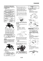
h. Install the washer "5", upper
bracket "6", washer "7", steering
stem nut "8", handlebar "9", han-
dlebar upper holder "10" and
headlight "11".
• The handlebar upper holder should
be installed with the punched mark
"a" forward.
• Install the handlebar so that the
marks "b" are in place on both
sides.
• Install the handlebar so that the pro-
jection "c" of the handlebar upper
holder is positioned at the mark on
the handlebar as shown.
• Insert the end of the fuel breather
hose "12" into the hole in the steer-
ing stem.
First tighten the bolts on the front
side of the handlebar upper holder,
and then tighten the bolts on the
rear side.
Steering nut wrench:
YU-33975/90890-01403
Steering nut wrench:
YU-33975/90890-01403
Steering ring nut (initial
tightening):
38 Nm (3.8 m•kg, 27
ft•lb)
Steering ring nut (final
tightening):
7 Nm (0.7 m•kg, 5.1
ft•lb)
Steering stem nut:
145 Nm (14.5 m•kg, 105
ft•lb)
Handlebar upper holder:
28 Nm (2.8 m•kg, 20
ft•lb)
Pinch bolt (upper brack-
et):
21 Nm (2.1 m•kg, 15
ft•lb)
Headlight:
7 Nm (0.7 m•kg, 5.1
ft•lb)
Summary of Contents for 2010 WR450FZ
Page 4: ......
Page 12: ...1 2 LOCATION OF IMPORTANT LABELS EUROPE ...
Page 13: ...1 3 LOCATION OF IMPORTANT LABELS AUS NZ ZA ...
Page 49: ...2 18 TIGHTENING TORQUES ...
Page 51: ...2 20 LUBRICATION DIAGRAMS 1 Intake camshaft 2 Exhaust camshaft A To main axle B From oil pump ...
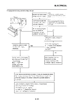
Page 90: ...3 31 ELECTRICAL Charging method using a variable voltage charger ...
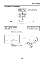
Page 91: ...3 32 ELECTRICAL Charging method using a constant voltage charger ...
Page 125: ...5 22 CYLINDER HEAD 3 Install Bolt cylinder head 1 Bolt cylinder head 10 Nm 1 0 m kg 7 2 ft lb ...
Page 144: ...5 41 OIL PUMP 15 Oil pump drive shaft 1 16 Rotor housing 1 Order Part name Q ty Remarks ...

