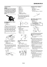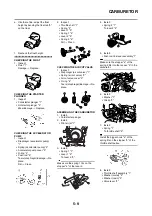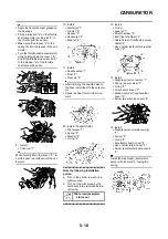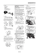
5-18
CAMSHAFTS
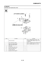
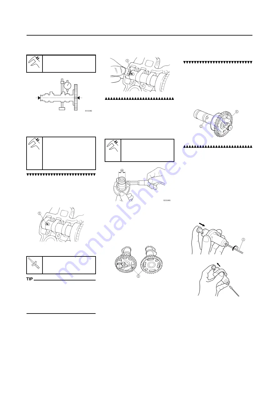
3. Measure:
• Runout (camshaft)
Out of specification
→
Replace.
4. Measure:
• Camshaft-to-cap clearance
Out of specification
→
Measure
camshaft outside diameter.
Measurement steps:
a. Install the camshaft onto the cylin-
der head.
b. Position a strip of Plastigauge
®
"1" onto the camshaft.
c. Install the clip, dowel pins and
camshaft caps.
• Tighten the bolts (camshaft cap) in
a crisscross pattern from innermost
to outer caps.
• Do not turn the camshaft when
measuring clearance with the
Plastigauge
®
.
d. Remove the camshaft caps and
measure the width of the Plasti-
gauge
®
"1".
5. Measure:
• Camshaft outside diameter "a"
Out of specification
→
Replace the
camshaft.
Within specification
→
Replace
camshaft case and camshaft
caps as a set.
CHECKING THE CAMSHAFT
SPROCKET
1. Inspect:
• Camshaft sprocket "1"
Wear/damage
→
Replace the
camshaft assembly and timing
chain as a set.
CHECKING THE
DECOMPRESSION SYSTEM
1. Check:
• Decompression system
Checking steps:
a. Check that the decompression
mechanism cam "1" moves
smoothly.
b. Check that the decompression
mechanism cam lever pin "2" proj-
ects from the camshaft.
CHECKING THE TIMING CHAIN
TENSIONER
1. Check:
• While pressing the tensioner rod
lightly with fingers, use a thin
screwdriver "1" and wind the ten-
sioner rod up fully clockwise.
• When releasing the screwdriver
by pressing lightly with fingers,
make sure that the tensioner rod
will come out smoothly.
• If not, replace the tensioner as-
sembly.
Runout (camshaft):
Less than 0.03 mm
(0.0012 in)
Camshaft-to-cap clear-
ance:
0.028–0.062 mm
(0.0011–0.0024 in)
<Limit>:0.08 mm (0.003
in)
Bolt (camshaft cap):
10 Nm (1.0 m•kg, 7.2
ft•lb)
Camshaft outside diame-
ter:
21.959–21.972 mm
(0.8645–0.8650 in)
Summary of Contents for 2010 WR450FZ
Page 4: ......
Page 12: ...1 2 LOCATION OF IMPORTANT LABELS EUROPE ...
Page 13: ...1 3 LOCATION OF IMPORTANT LABELS AUS NZ ZA ...
Page 49: ...2 18 TIGHTENING TORQUES ...
Page 51: ...2 20 LUBRICATION DIAGRAMS 1 Intake camshaft 2 Exhaust camshaft A To main axle B From oil pump ...
Page 90: ...3 31 ELECTRICAL Charging method using a variable voltage charger ...
Page 91: ...3 32 ELECTRICAL Charging method using a constant voltage charger ...
Page 125: ...5 22 CYLINDER HEAD 3 Install Bolt cylinder head 1 Bolt cylinder head 10 Nm 1 0 m kg 7 2 ft lb ...
Page 144: ...5 41 OIL PUMP 15 Oil pump drive shaft 1 16 Rotor housing 1 Order Part name Q ty Remarks ...

