7-11
ELECTRIC STARTING SYSTEM
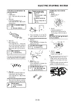
CHECKING AND REPAIRING THE
STARTER MOTOR
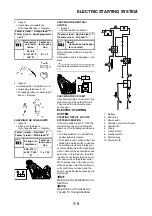
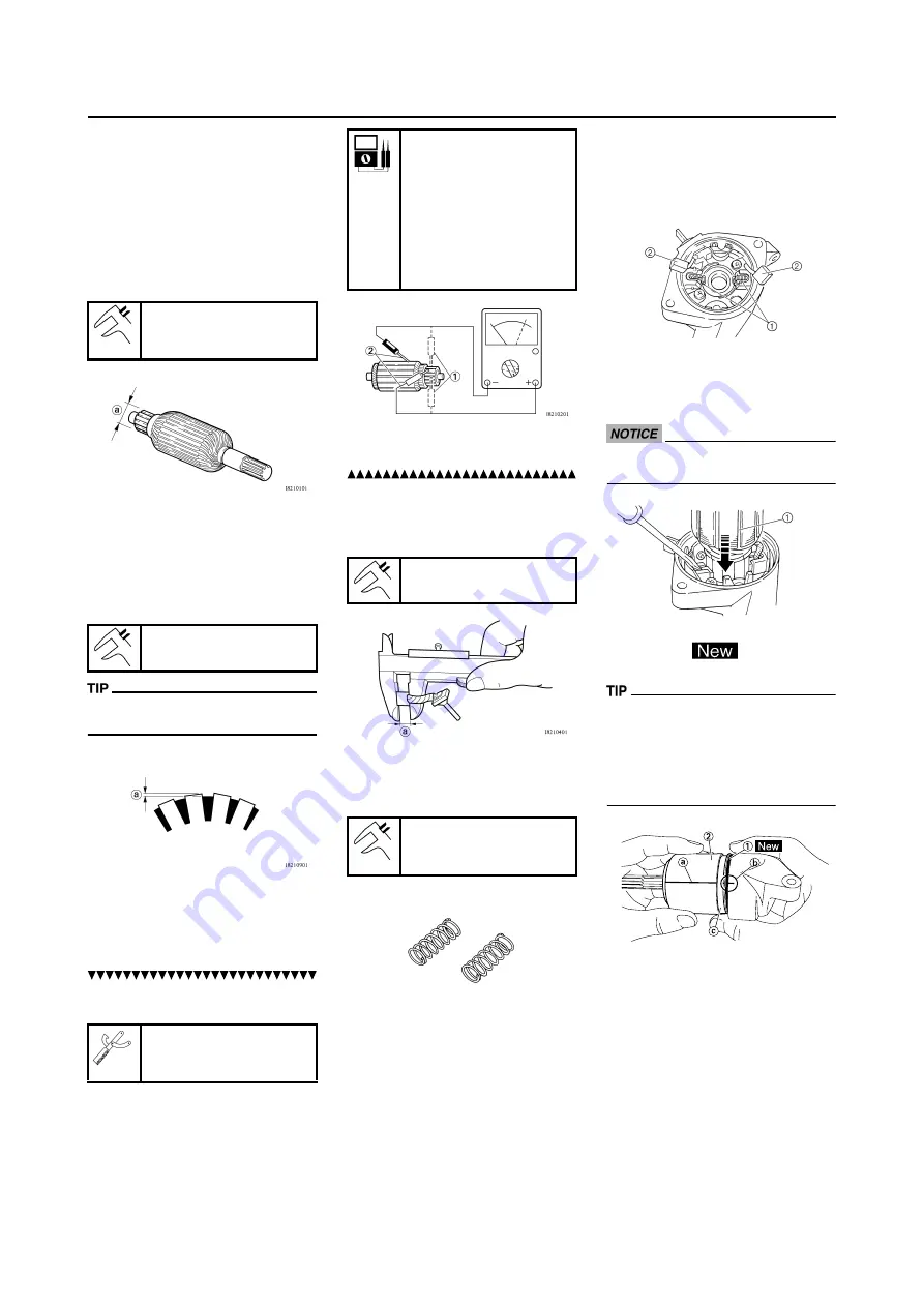
1. Check:
• Commutator
Dirt
→
Clean with 600 grit sandpa-
per.
2. Measure:
• Commutator diameter "a"
Out of specification
→
Replace the
starter motor.
3. Measure:
• Mica undercut "a"
Out of specification
→
Scrape the
mica to the proper measurement
with a hacksaw blade which has
been grounded to fit the commu-
tator.
The mica must be undercut to ensure
proper operation of the commutator.
4. Measure:
• Armature assembly resistances
(commutator and insulation)
Out of specification
→
Replace the
starter motor.
a. Measure the armature assembly
resistances with the pocket tester.
b. If any resistance is out of specifi-
cation, replace the starter motor.
5. Measure:
• Brush length "a"
Out of specification
→
Replace the
brushes as a set.
6. Measure:
• Brush spring force
Out of specification
→
Replace the
brush springs as a set.
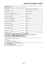
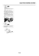
ASSEMBLING THE STARTER
MOTOR
1. Install:
• Brush spring "1"
• Brush "2"
2. Install:
• Armature assembly "1"
Install while holding down the
brush using a thin screw driver.
Be careful not to damage the brush
during installation.
3. Install:
• O-ring "1"
• Starter motor yoke "2"
• Align the match mark "a" on the
starter motor yoke with the match
mark "b" on the starter motor rear
cover.
• Install the starter motor yoke with its
groove "c" facing rear cover.
Min. commutator diame-
ter:
16.6 mm (0.65 in)
Mica undercut:
1.5 mm (0.06 in)
Pocket tester:
YU-3112-C/90890-
03112
Armature assembly:
Commutator resis-
tance "1":
0.0117–0.0143
Ω
at 20
°C (68 °F)
Insulation resistance
"2":
Above 1 M
Ω
at 20 °C
(68 °F)
Min. brush length:
3.5 mm (0.14 in)
Brush spring force:
3.92–5.88 N (400–600
gf, 14.1–21.2 oz)
Summary of Contents for 2010 WR450FZ
Page 4: ......
Page 12: ...1 2 LOCATION OF IMPORTANT LABELS EUROPE ...
Page 13: ...1 3 LOCATION OF IMPORTANT LABELS AUS NZ ZA ...
Page 49: ...2 18 TIGHTENING TORQUES ...
Page 51: ...2 20 LUBRICATION DIAGRAMS 1 Intake camshaft 2 Exhaust camshaft A To main axle B From oil pump ...
Page 90: ...3 31 ELECTRICAL Charging method using a variable voltage charger ...
Page 91: ...3 32 ELECTRICAL Charging method using a constant voltage charger ...
Page 125: ...5 22 CYLINDER HEAD 3 Install Bolt cylinder head 1 Bolt cylinder head 10 Nm 1 0 m kg 7 2 ft lb ...
Page 144: ...5 41 OIL PUMP 15 Oil pump drive shaft 1 16 Rotor housing 1 Order Part name Q ty Remarks ...

