3-24
CHASSIS
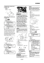
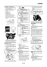
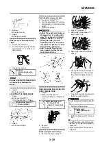
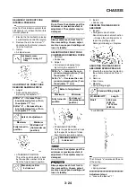
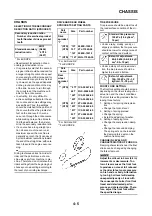
RELIEVING THE FRONT FORK
INTERNAL PRESSURE
If the front fork initial movement feels
stiff during a run, relieve the front fork
internal pressure.
1. Elevate the front wheel by placing
a suitable stand under the engine.
2. Remove the air bleed screw "1"
and release the internal pressure
from the front fork.
3. Install:
• Air bleed screw
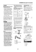
ADJUSTING THE FRONT FORK
REBOUND DAMPING FORCE
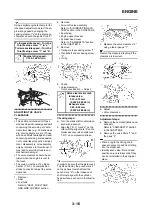
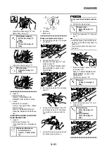
1. Adjust:
• Rebound damping force
By turning the adjuster "1".
• STANDARD POSITION:
This is the position which is back
by the specific number of clicks
from the fully turned-in position.
Do not force the adjuster past the
minimum or maximum extent of
adjustment. The adjuster may be
damaged.
Always adjust each front fork to
the same setting. Uneven adjust-
ment can cause poor handling and
loss of stability.
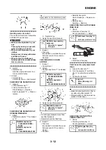
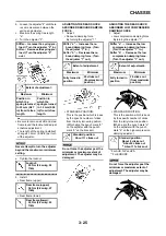
ADJUSTING THE FRONT FORK
COMPRESSION DAMPING FORCE
1. Remove:
• Rubber cap
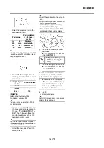
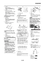
2. Adjust:
• Compression damping force
By turning the adjuster "1".
• STANDARD POSITION:
This is the position which is back
by the specific number of clicks
from the fully turned-in position.
Do not force the adjuster past the
minimum or maximum extent of
adjustment. The adjuster may be
damaged.
Always adjust each front fork to
the same setting. Uneven adjust-
ment can cause poor handling and
loss of stability.
3. Install:
• Rubber cap
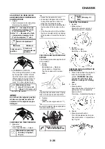
CHECKING THE REAR SHOCK
ABSORBER
1. Inspect:
• Swingarm smooth action
Abnormal noise/unsmooth action
→
Grease the pivoting points or
repair the pivoting points.
Damage/oil leakage
→
Replace.
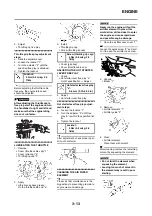
ADJUSTING THE REAR SHOCK
ABSORBER SPRING PRELOAD
1. Elevate the rear wheel by placing
the suitable stand under the en-
gine.
2. Remove:
• Rear frame
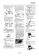
3. Measure:
• Spring fitting length
The I.D. mark "a" is marked at the end
of the spring.
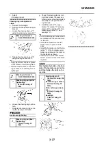
4. Adjust:
• Spring preload
Adjustment steps:
a. Loosen the locknut "1".
Air bleed screw:
1 Nm (0.1 m•kg, 0.7
ft•lb)
Stiffer "a"
→
Increase the re-
bound damping force. (Turn
the adjuster "1" in.)
Softer "b"
→
Decrease the re-
bound damping force. (Turn
the adjuster "1" out.)
Extent of adjustment:
Maximum
Minimum
Fully turned in
position
20 clicks out
(from maximum
position)
Standard position:
8 clicks out
Stiffer "a"
→
Increase the com-
pression damping force. (Turn
the adjuster "1" in.)
Softer "b"
→
Decrease the com-
pression damping force. (Turn
the adjuster "1" out.)
Extent of adjustment:
Maximum
Minimum
Fully turned in
position
20 clicks out
(from maximum
position)
Standard position:
9 clicks out
Standard fitting length:
I.D. MARK/Q'TY
Length
Pink/1
252.5 mm
(9.94 in)
* 251.5 mm
(9.90 in)
* For EUROPE
Summary of Contents for 2010 WR450FZ
Page 4: ......
Page 12: ...1 2 LOCATION OF IMPORTANT LABELS EUROPE ...
Page 13: ...1 3 LOCATION OF IMPORTANT LABELS AUS NZ ZA ...
Page 49: ...2 18 TIGHTENING TORQUES ...
Page 51: ...2 20 LUBRICATION DIAGRAMS 1 Intake camshaft 2 Exhaust camshaft A To main axle B From oil pump ...
Page 90: ...3 31 ELECTRICAL Charging method using a variable voltage charger ...
Page 91: ...3 32 ELECTRICAL Charging method using a constant voltage charger ...
Page 125: ...5 22 CYLINDER HEAD 3 Install Bolt cylinder head 1 Bolt cylinder head 10 Nm 1 0 m kg 7 2 ft lb ...
Page 144: ...5 41 OIL PUMP 15 Oil pump drive shaft 1 16 Rotor housing 1 Order Part name Q ty Remarks ...

