


Operation Manual
45
Operator Cab
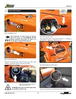
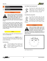
Fig 46. Boom Control
Handle Functions
A
B
C
D
E
F
G
H
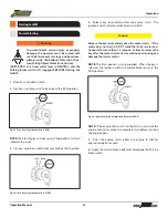
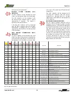
Attachment Tilt Switch
The Attachment Tilt Switch located on the top of the boom
control handle controls attachment tilt functions.
The Attachment Tilt Switch:
•
Controls the attachment tilt functions by rolling the
switch forward and backward.
•
Is a variable speed switch. Function speed is proportion-
al to how far the switch is rolled. The more the switch is
rolled in the appropriate direction, the faster the corre-
sponding function will occur.
ATTACHMENT TILT DOWN
ATTACHMENT TILT UP
Roll switch forward away from
the operator
Roll switch backward toward
the operator
Attachment Tilt Switch
Function
Handle Action
Fig 48. Attachment Tilt Control Switch.
(A) Attachment Tilt Down. (B) Attachment Tilt Up
NOTE: The attachment carriage will retain any set angle
throughout boom raising, lowering, retracting, or extending
operations.
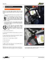
Frame Sway Control Handle
The Frame Sway Control Handle installed on the side console
panel, controls frame sway functions.
Fig 49. Frame Sway Control Handle
NOTE: The attachment carriage will retain any set angle
throughout boom raising, lowering, retracting, or extending
operations.
The Frame Sway Control Handle installed on the side console
panel, controls frame sway functions.
The Frame Sway Control Handle:
•
Controls the frame sway functions by moving the control
handle left and right.
•
Is a variable speed control. Function speed is proportional
to control handle movement. The more the control han-
dle is moved in the appropriate direction, the faster the
corresponding function will occur.
NOTE: Lock the frame sway by placing the travel select lever
in NEUTRAL or applying the service or parking brake.


