background image

Operation Manual

43

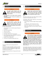
Operator Cab

Fig 38.  User Settings

UTILITIES 
Pressing the UTILITIES soft button will bring up another menu.

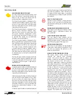
Fig 40.  Utilities  

Fig 39.  System Settings 

SYSTEM SETTINGS 
Pressing the SYSTEM SETTINGS soft button will display 

communication parameters. Pressing the MENU button will 

return to the UTILITIES mode.  

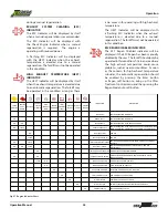
SERVICE REMINDERS 
Pressing the SERVICE REMINDERS soft button will display data 

pertaining to maintenance schedules.  Pressing the MENU 

button will return to the UTILITIES mode.

Fig 41.  Service Reminders  

PDM DIAGNOSTICS 
Pressing the PDM DIAGNOSTICS soft button will display the 

status of the Power Distribution Module.  

Fig 42.  PDM Diagnostics

Summary of Contents for XR3034

Page 1: ...Operation and Safety Manual PN 24941 001 Tier 4 Final ...

Page 2: ...a California In October 2013 Xtreme became the majority shareholder in Snorkel a global aerial work platform manufacturer which has manufacturing facilities in the US UK New Zealand as well as a global sales distribution network Find out more about Snorkel at www snorkellifts com Xtreme Manufacturing 8350 Eastgate Road Henderson NV 89015 USA Contact Us T 1 800 497 1704 T 1 702 636 2969 F 1 702 636...

Page 3: ...g Controls If So Equipped 35 Table of Contents Description Page Operator Seat 35 Operator Seat Controls 35 Weight Suspension Lever 36 Lumbar Support 36 Fore and Aft Adjustment Lever 36 Backrest Angle Adjustment Lever 36 Seat Belt 37 Rear View Mirrors 37 Controls and Indicators 38 Travel Select Lever 38 Gear Select Switch 38 Parking Brake Switch 38 Load Capacity Charts 38 Light Switches 39 Turn Sig...

Page 4: ...iage Operation 61 Fork Positioning Carriage Operation 62 Quick Attach System 62 Load Handling 64 Boom Lift Point 65 Description Page Suspended Loads 65 Pick Up a Load 65 Carry a Load 66 Place a Load 66 Tow Pin Pintle Hook Optional 66 Load Shift 66 Elevating Personnel 67 Frame Leveling 68 Load Capacity Charts 69 Preventive Maintenance Preventive Maintenance 71 Establishing a Maintenance Program 71 ...

Page 5: ... and practice safe use of forklift controls in a safe clear area BEFORE you operate this forklift on a work site It is your responsibility to observe applicable laws and regulations and to follow manufacturer s instructions on forklift operation and maintenance Replacement manuals for the XR3034 Reach Forklift can be obtained by contacting our parts department by phone or visiting our website Xtre...

Page 6: ...Disclaimer CAUTION Yellow with the safety alert sym bol indicates a potentially hazardous situa tion which if not avoided could result in mi nor or moderate injury Caution Caution Warning Safety Symbols WARNING Orange used with the safety alert symbol indi cates a potentially hazardous situation which if not avoid ed could result in death or serious injury Warning CAUTION Yellow used without the s...

Page 7: ...e If Using Alcohol Drugs Or Medications Personal Protective Equipment Safety Shoes Lead Acid Batteries Create Explosive Gases Warning Hydraulic Oil Under Pressure Hot Oil DO NOT Open Unless Cap Is Cool To Touch Warning Rotating Belts Can Cut Or Entangle Replace Worn And Illegible Safety Labels And Labels Read Maintenance Manual Before Working On This Forklift Know First Aid Instructions And Or Loc...

Page 8: ...Brake Warning Forklift Tip Over Can Cause Death Or Serious Injury DO NOT Raise Boom While Traveling On A Slope Danger Keep A Safe Distance From Electrical Lines Pinch Points Hands DO NOT Use Ether As A Starting Aid DO NOT Allow Riders On Auxiliary Attachments Set Parking Brake To OFF Disengage Parking Brake DO NOT Jump If Forklift Tips Keep Seat belt ON And Brace Yourself Tip Over Hazard Especiall...

Page 9: ...fication or alter ation including welding or drilling can im pair and weaken the protective capability of the Rollover Protective Structure Falling Object Protective Structure ROPS FOPS and could result in death or serious injury Replace the ROPS FOPS if it is damaged before operating the forklift Under Occupational Safety and Health Administration OSHA rules employers are required to train worker...

Page 10: ...erground objects could cause death or serious injury Warning Theforkliftisdesignedtohandleroughterrain however operating the forklift where large holes obstructions debris loose fill and other work site hazards exist could result in death or serious injury DO NOT allow bystanders in the work area Avoid personnel machinery and vehicles in the work area Know the rules for movement of people and vehi...

Page 11: ...ons and functional tests may require assistance Keep the assistant visible and a safe distance from the forklift to prevent death or serious injury Become familiar with all safety and hazard labels regulations and procedures Make sure all proper safety and hazard labels are attached to the forklift and remain legible A brief description of controls indicators and instruments is provided as a conve...

Page 12: ... above horizontal If Remain securely fastened in the seat belt Keep your head body and limbs within the ROPS FOPS structure Brace yourself and hold on firmly Lean away from the point of impact Stay on the forklift and ride out the roll over or tip over the forklift cannot be leveled using the frame sway control do not attempt to raise or place load Reposition forklift or have the surface leveled W...

Page 13: ...ifting to the next lower gear Improper use of the gear select lever could cause transmission damage or forklift tip over roll over and result in death or serious in jury Operate the forklift for maximum stability Unstable forklifts can tip over resulting in death serious injury or property damage Keep the forklift stable by following these and other appropriate guidelines Adjust speed for terrain ...

Page 14: ...epair the forklift BEFORE placing it into service again Ignoring warning indicators can result in death serious injury or property damage Contact with hot surfaces and the exhaust pipe after the forklift has been operated could result in serious personal injury Check warning indicators and gauges on the dash panel frequently during operation If a warning indicator is illuminated or a gauge shows a...

Page 15: ...g valve or is rated to be equal or greater than 4 300 psi 296 5 bar which is the maximum pressure of the forklift auxiliary hydraulic system at the quick disconnect couplers could result in death or serious injury Make sure all hydraulic connections are tight if equipped Shut Down Procedure Warning To prevent death or serious injury follow these procedures before leaving the forklift cab Park fork...

Page 16: ...rting procedures and engine manufac turer s specifications for using a starting aid Lead acid batteries produce flammable and potentially ex plosive gases To avoid death or serious injury when check ing testing or charging batteries DO NOT use smoking materials near batteries Keep arcs sparks and open flames away from batteries Provide ventilation for flammable vapors Wear proper personal protecti...

Page 17: ... four wheels to prevent the vehicle from moving once the parking brake is disabled 2 Position the towing vehicle in place Attach any chain needed to secure the disabled vehicle 3 Crawl under the front of the vehicle Locate the parking brake assembly 4 Remove dust cover cap and set aside 5 Release lock nut Turn adjusting screw counter clockwise until brake disc is free Tighten lock nut Parking brak...

Page 18: ...ng brake disabled 2 Crawl under the front of the vehicle Locate the parking brake assembly 3 Remove dust cover cap and set aside 4 Release locknut Turn adjusting screw clockwise until brake disc is fully engaged Turn adjusting screw counter clockwise 1 2 turn Tighten lock nut Parking brake is now re activated 5 Re install dust cover cap and tighten 6 Verify the parking brake works 7 Remove any war...

Page 19: ...Operation Manual 19 Labels Left Side View Labels Fig 6 Label Legend Cab Side 35 41 37 38 26 25 41 10 12 34 56 3 17 10 5 36 9 24 32 33 45 46 47 31 ON CHASSIS 31 ON CHASSIS 43 ON GLASS ...

Page 20: ...Operation Manual 20 Fig 7 Label Legend Tank Side Right Side View 35 39 41 40 24 9 36 43 33 32 25 41 10 12 34 3 25 10 28 7 06 4 19 27 31 ON CHASSIS 31 ON CHASSIS 51 8 26 ON CHASSIS INSIDE COVER ...

Page 21: ...ion Manual 21 Labels Front View Cab View Fig 8 Label Legend Front Fig 10 Label Legend Cab Rear View Fig 9 Label Legend Rear 10 21 1 16 18 15 11 20 2 36 25 12 13 32 33 24 10 12 34 41 44 48 22 50 53 55 54 56 57 ...

Page 22: ...E SMALL GREEN 26 2 18066 001 LABEL CAUTION CRUSHING 27 1 18069 000 DECAL XRM HYDRAULIC LEVEL 04 28 1 18082 001 LABEL WARNING INJECTION HAZARD 29 2 18083 001 LABEL WARNING EXPLOSION HAZARD Item Qty Part No Description Table 1 Labels 30 1 18086 001 LABEL DEXRON III 31 4 18090 001 LABEL WARNING TIP OVER HAZARD 32 2 18300 001 LABEL WARNING FALLING HAZARD 33 2 18312 000 LABEL WARNING FALLING HAZARD 34 ...

Page 23: ...JURY may result from slipping or tripping CAUTION WATCH YOUR STEP while entering or exiting 2 18004 070 4 18011 001 6 18014 002 CHECK ENGINE OIL 18014 002 Minimum Oil Specification API CJ 4 or higher 18004 070 702 636 2969 800 497 1704 www XMFG com Parking Brake OFF ON Front On Off Lights Boom Rear Wiper Wash On Off Hazard Turn Steering 4W 2W Crab Front and Rear Wheels Must Be Centered Before Enga...

Page 24: ...Operation Manual 24 Labels 7 18015 001 8 18016 001 11 18018 002 12 18019 001 9 18017 001 10 18018 001 ...

Page 25: ...Operation Manual 25 Labels 13 18020 001 14 18021 001 17 18025 001 18 18026 001 15 18022 001 16 18023 001 ...

Page 26: ...Operation Manual 26 Labels 19 18027 001 20 18031 001 23 18039 000 24 18041 001 21 18032 001 WARNING 22 18033 000 AUXILIARY AUXILIARY 18033 000 ...

Page 27: ... 27 Labels 25 18042 000 26 18066 001 18066 001 CAUTION CRUSHING HAZARD VEHICLE DAMAGE may result from leaving hood open CLOSE HOOD before lowering boom 29 18083 001 30 18086 001 27 18069 000 FULL 18069 000 28 18082 001 ...

Page 28: ...Operation Manual 28 Labels 31 18090 001 32 18300 001 35 18043 000 36 18044 000 18044 000 33 18312 000 34 18315 000 18315 000 ...

Page 29: ... 000 42 18409 000 DIESEL EXHAUST FLUID DEF ONLY 18409 000 39 18353 000 18353 000 40 18346 000 18346 000 43 18311 010 18311 010 24 000 lbs 44 18331 000 DAMAGE may result from adjusting forks when carriage is loaded CARRIAGE DAMAGE ONLY ADJUST FORKS WHEN CARRIAGE IS UNLOADED 18331 000 ...

Page 30: ...LBS Max tow capacity 5000 LBS DO NOT ELEVATE BOOM ABOVE 30 WHEN TOWING 50 18412 000 18412 000 CAUTION EQUIPMENT DAMAGE Wait at least two 2 minutes after shutting engine off before setting the battery disconnect switch to OFF Equipment damage may occur if the engine ECM and DEF systems are not allowed to shutdown properly 51 18307 001 18307 001 WARNING FALLING HAZARD DEATH or SERIOUS INJURY could r...

Page 31: ... CARRIAGE 5FT LOAD CENTER P N 17095 000 04 LOAD RATINGS SHOWN ARE FOR VEHICLES EQUIPPED WITH FOAM FILLED TIRES ONLY 7 750 LBS AT 60 IN MIN CAPACITY FORK 15 500 LBS PAIR BO O M A N G LE 15 5 00 LB S 15 1 00 LB S 12 1 00 LB S 9 80 0 LB S FORKS MUST BE 8FT LONG WHEN USING 5FT LOAD CENTER 56 18413 000 57 18081 000 ...

Page 32: ...electrical system Display with fuel level engine coolant temperature oil pressure tachometer DEF level and battery voltage gauges and brake oil pressure parking brake axle lock rear wheel alignment and tilt interlock warning indicators brake oil pressure parking brake axle lock rear wheel alignment and tilt interlock warning lights Easy access drop down electrical panel 12 Volt accessory power out...

Page 33: ...vy duty Frame Chassis Heavy duty Roller Boom Melonite Pins and Rollers Direct Dual Control Hydraulic Valve Actuation Robust Wiring No Spades No Pins Rear Axle Stabilization RAS Center Inline Engine Drive Train Full time Planetary 4 Wheel Drive Steering 4 Wheel Circle Crab 2 Wheel Front Back Up Alarm Open ROPS FOPS Adjustable Hydraulic Operator Controls Suspension Seat Quick Attach Common Fit Xtrem...

Page 34: ...d Ignition Switch The ignition switch has three 3 positions OFF RUN and START Ignition Switch Position Purpose OFF Shuts down entire electrical system except the accessory outlet RUN All controls and indicators are operable START Engages starter motor to crank engine NOTE The START position is spring loaded When the key is released the Ignition switch will automatically return to the RUN position ...

Page 35: ...seat can be adjusted four 4 ways weight suspension height fore and aft and backrest angle Fig 18 Operator Seat Operator Seat Air Conditioning Controls If the Cab is equipped with air conditioning the controls are next to the operator seat Use the top rotary knob A to con trol the fan speed Use the bottom rotary knob to control the air temperarure Use the switch C to turn the A C on or off Fig 17 A...

Page 36: ...r decrease the lumbar support Fig 20 Lumbar Support Fore and Aft Adjustment Lever Pull the fore and aft adjustment lever outward from the seat to release the seat lock Slide the seat forward or backward to a comfortable location and release the lever to lock the seat in the desired position Fig 21 Fore and Aft Adjustment Lever Backrest Angle Adjustment Lever Pull the backrest angle adjustment leve...

Page 37: ... at least one hand on the wheel while the forklift is moving to prevent loss of forklift control which could result in death or serious injury Before starting the engine adjust the seat for position and comfort refer to the Operator Seat section of this manual and then adjust the seat belt as follows 1 Grasp the free end of the seat belt located on the left side of the seat and make sure the belt ...

Page 38: ...play switches to the back up camera view Gear Select Switch TheGearSelectswitchhasatwistgriphandlewithmomentary up and momentary down positions for six 6 forward and three 3 reverse gears NOTE Transmission gear range can also be changed on the joystick with the Drive Speed thumb switch Fig 27 Gear Select Switch Parking Brake Switch The Parking Brake switch A has two 2 positions ON and OFF Fig 28 P...

Page 39: ...eering Select switch has three 3 steering positions Crab TwoWheel Steering 2W and FourWheel Steering 4W Fig 32 Steering Select Switch Warning DO NOT change steering modes until the forklift slows or comes to a complete stop Align all four 4 wheels perpendicular to the axle before changing steering mode Changing steering modes at higher travel speeds can make the forklift unstable and cause a loss ...

Page 40: ...he engine G ENGINE SERVICE REQUIRED The Engine Service Required Indicator will be displayed when a maintenance interval has been exceeded H REGENERATION MENU Pushing the soft button adjacent to the Regen Menu indica tor displays the exhaust system regeneration mode with the available options Fig 43 I REAR AXLE LOCKED The Rear Axle Locked Indicator illuminates when the forklift is in the axle lock ...

Page 41: ...hut down or an engine shutdown is imminent T CHECK ENGINE GENERAL WARNING INDICATOR In case of any engine errors the general error lamp of the engine will be activated Whenever the error lamp is active a fault code is stored in the error memory Two different states are possible Solid on Errors that allow continuing engine operation with minor restrictions Blinking Errors that cause an engine shut ...

Page 42: ...ing the MENU button again or the GAUGE DISPLAY soft button will return to the GAUGE DISPLAY mode ENGINE DIAGNOSTICS Pressing the ENGINE DIAGNOSTICS soft button will display engine information Pressing the MENU button will return to the GAUGE DISPLAY mode Fig 37 Engine Diagnostics Soft Buttons Soft Buttons Menu Button Enter Button V HIGH EXHAUST TEMPERATURE HEST The High Exhaust Temperature HEST in...
Page 43: ... display communication parameters Pressing the MENU button will return to the UTILITIES mode SERVICE REMINDERS Pressing the SERVICE REMINDERS soft button will display data pertaining to maintenance schedules Pressing the MENU button will return to the UTILITIES mode Fig 41 Service Reminders PDM DIAGNOSTICS Pressing the PDM DIAGNOSTICS soft button will display the status of the Power Distribution M...

Page 44: ...an only be initiated if the system is requesting it Pressing the ENTER button will return to the GAUGE DISPLAY mode Fig 43 Regeneration Menu FAULT CONDITION POP UPS A fault condition may trigger a pop up dialog box describing the nature of the fault A soft button may need to be pressed to acknowledge the fault NOTE Increasing engine speed can increase boom lift and extend speed BACKUP CAMERA OPTIO...

Page 45: ...Tilt Down B Attachment Tilt Up NOTE The attachment carriage will retain any set angle throughout boom raising lowering retracting or extending operations Frame Sway Control Handle The Frame Sway Control Handle installed on the side console panel controls frame sway functions Fig 49 Frame Sway Control Handle NOTE The attachment carriage will retain any set angle throughout boom raising lowering ret...

Page 46: ... SWAY RIGHT FRAME SWAY LEFT Move Control Handle RIGHT Move Control Handle LEFT Frame Sway Control Handle Function Handle Action NOTE Maximum frame sway is 16 overall or 8 each direc tion left and right Warning The reach forklift includes a Frame Sway Override switch Improper use of the Frame Sway Override switch could cause death se rious injury or property damage Fig 50 Frame Sway Override Switch...

Page 47: ...uip ment used to support the boom during any and maintenance activities where the boom is raised When preparing to set boom stand make sure machine is on a flat level ground and machine has no load on the forks Raise machine boom to 40 degrees for clearance and re Boom Maintenance Stand If So Equipped All the attachments should be stored in an appropriate enclosure as to prevent corrosion and dete...

Page 48: ...the seat belt or mounting hardware is defective it may not properly restrain the operator resulting in death or serious injury DO NOT operate the forklift until the seat belt or mount ing hardware is replaced if worn or damaged The seat belt MUST be worn while operating the fork lift Failure to wear the seat belt could result in death or serious injury Pre Operation Inspection To perform the pre o...

Page 49: ...have proper ballast DO NOT replace foam filled tires with pneumatic tires Use of pneumatic tires will severely affect vehicle load capacity which could result in death serious injury or property damage Warning Wear eye protection when connecting jump start cables Improper jump start procedures could cause the battery to explode which could result in death or serious injury Never jump start a froze...

Page 50: ...ft Check that load capacity charts are legible Check that frame level indicator is working properly Check condition and operation of the seat belt and mounting hardware Check that Operation and Safety Manual is in the protective case and legible Check forks for welds cracks misalignment or any other damage Check all hydraulic hoses and hose connections for wear or leaks Check tilt cylinders for le...

Page 51: ...e gear select lever and or thumb switch while operating the forklift in forward and reverse Test the service and parking brakes Apply the service brake pedal after the forklift begins to move and the forklift should stop immediately Apply the parking brake The forklift should not move unless the parking brake is released Test each steering function Operate the forklift in forward and reverse at lo...

Page 52: ...is displayed Fill DEF tank at each fuel fill Check Hydraulic Oil Sight Gauge A Add Hy draulic Oil if Necessary B WARNING DO NOT Remove Hydraulic Tank Filler Cap Unless It Is Cool Enough To Touch With Bare Hands Check Engine Oil Level Using Yellow Dipstick A Add Engine Oil API CJ 4 If Necessary B See Inset WARNING Hot Coolant DO NOT Open Radia tor Cap When Hot To Touch A B INSET A B Fig 57 Check Co...

Page 53: ... pedals levers or other protrudingparts Landingonunevensurfaces could result in death or serious personal injury NOTE The engine will only start when the travel select lever is in NEUTRAL N and the Parking Brake switch is ON engaged Fig 61 Travel Select Lever Must Be In Neutral N To Start The Reach Forklift Fig 62 Parking Brake Switch A Must Be On Engaged To Start The Reach Forklift Parking Brake ...

Page 54: ...e starter motor con tinuously for more than 15 seconds Failure to release the key after the motor has started or continuous cranking can damage the starter motor 4 Release key immediately after the engine starts The Ignition Switch will automatically return to RUN Fig 65 Ignition Switch Automatically Returns to RUN NOTE If the engine fails to start on the first try wait until the engine and starte...

Page 55: ...the dash panel to change steering modes Crab steering allows all four 4 wheels to turn in the same direction as the steering wheel allowing the forklift to move sideways Crab steering is useful in a congested work site to line up to a loading location Crab Steering Two wheel 2W steering allows the front wheels to turn in the same direction as the steering wheel The rear wheels remain in a fixed fo...

Page 56: ...afety procedures and avoid hazardous situations while operating the forklift to prevent death serious injury or property damage Check the work site for any hazards before operating the forklift Check the work surface for loose soil conditions and overhead power lines Starting Travel Warning Indicators Warning A fault condition may trigger a popup dialog box on the display describing the nature of ...

Page 57: ...shutdown in some conditions A steady Engine Shutdown Indicator displayed Operation TIER IV FINAL ENGINE with the Check Engine Indicator and a flashing Low DEF Level Indicator shows the DEF tank is empty and the engine power is operating at reduced power or limited to idle add DEF immediately WAIT TO START INDICATOR The Wait to Start Indicator is displayed when the key switch is moved to the RUN po...

Page 58: ...ation EXHAUST SYSTEM CLEANING ESC INDICATOR The ESC Indicator will be displayed by itself when a manual regeneration is recommended The ESC Indicator will be displayed with the Check Engine Indicator when a manual regeneration is required The engine is operating with reduced power A flashing ESC Indicator will be displayed with the HEST Indicator when the exhaust temperature is elevated due to a m...

Page 59: ...sible 2 Stop the forklift by applying the service brake pedal 3 Place the travel select lever in NEUTRAL N and set the parking brake to ON engaged 4 Lower the boom and rest carriage on ground or raise and retract boom 5 Turn the ignition key to OFF and remove the key 6 If the forklift is parked on an incline chock the wheels Shut Down Procedure Caution DO NOT leave the reach forklift unattended du...

Page 60: ...y be needed in higher altitude or an extremely low temperature climate to prevent misfiring and excessive smoke Use only Ultra Low Sulfur fuel Maximum sulfur content 15 ppm Use of improper grade of fuel may result in damage to en gine or exhaust aftertreatment system Caution Engine fuel is flammable and can cause a fire or explosion resulting in death or serious in jury DO NOT smoke while refu eli...

Page 61: ...t the individual fork can safely carry at a maximum load center of 36 inches 914 mm Fig 69 Fork Ratings A Maximum Load Capacity Rating B 36 inch Load Center Because forks are always used in multiples the total rating of any combination of forks will be the sum of their rated capacity Other than block forks all forks should be used in matched pairs Block forks should be used in matched sets The max...

Page 62: ...ulic pressure rating Failure to make sure the attachment is equipped with a pressure reducing valve or is rated to be equal or slightly greater than 4 000 psi 276 bar which is the maximum pressure of the forklift auxiliary hydraulic system at the quick disconnect couplers could result in death or serious injury Make sure all hydraulic connections are tight if equipped 1 Position the forklift direc...

Page 63: ... with a pressure reducing valve or is rated to be equal or slightly greater than 4 000 psi 276 bar which is the maximum pressure of the forklift auxiliary hydraulic system at the quick disconnect couplers could result in death or serious injury Make sure all hydraulic connections are tight if equipped A Fig 74 Drive Vehicle Forward To Align Pivot Pins with Attachment Hooks A B Fig 77 Retaining Pin...

Page 64: ...exceed forklift capacity Forks can bend or break causing loss of load and could result in death or serious injury DO NOT exceed the manufacturer s rated load for any auxiliary attachment Any attempt to lift or carry loads in excess of the manufactur er s rated load may cause forklift tip over loss of load or structural damage which could re sult in death serious injury or property damage Warning D...

Page 65: ...ad to swing and create a hazard if not stabilized Swinging loads can become unstable and could cause death serious injury or property damage Suspended Loads Fig 81 Boom Lift Point There is a boom lift point on the underside of the boom that may be used to lift and carry loads There is a dedicated boom lift point load chart available which should be referenced when using the boom lift point Refer t...

Page 66: ...er its weight 3 If the load shift is too great for adjustment rearrange the load before attempting to move the forklift Tow Pin Pintle Hook Optional Warning Death or serious injury could result from improper operation when using the tow connection Do not elevate the boom above 300 when towing Do not exceed rated tow capacity 500 LBS vertical load 5 000 LBS tow capacity The Pintle Hook is used for ...

Page 67: ...ires plus 10 on each side 4 Minimum space requirements for each person on the platform shall not be less than 18 in either direction 5 4 minimum height toe plate around the perimeter of the platform which may be omitted at the access opening 6 On the overhead protection device when requested by the user 7 Protection must be provided for the personnel in their normal working position on the platfor...

Page 68: ... the area around and under the work platform should be marked to warn anyone on the ground that overhead work is being done 21 The platform shall be lowered to ground level for personnel to enter and exit Personnel shall not climb on any part of the rough terrain forklift in attempting to enter and exit 22 Protection must be provided for the personnel on the work platform from pinch points or movi...

Page 69: ...based on the forklift being on firm level ground the forks being evenly positioned on the carriage the load being centered on the forks properly sized tires properly inflated and or foam filled and the forklift being in good operating condition Load capacity charts located on the left side of the dash panel are provided to assist the operator in determining how to safely operate the boom to pick u...

Page 70: ...S 15 000 LBS AT 24 IN MIN CAPACITY FORK 30 000 LBS PAIR Fig 89 Load Capacity Chart For example 1 The operator determines load weight and makes sure load does not exceed fork attachment or boom capacity The load is 15 000 pounds 6804 kg 2 The operator safely moves the load to a loading position Places forks under load Tilts and raises load safely Fully retracts boom Drives forklift to position perp...

Page 71: ...t grease fittings Change differential oil Change wheel end oil Check wheel lug nuts torqued to 380 420 ft lbs Lubricate boom pivot point grease fittings Lubricate boom roller grease fittings Replace hydraulic return line filters Replace transmission filter and top off fluid as required Every Day or 8 Hours of Operation See Pre Operation Inspection Checklist After First 50 Hours of Operation Lubric...

Page 72: ...aulic return line filters Replace hydraulic high pressure filters After Every 500 Hours of Operation Comply with 50 Hour Maintenance Requirements Comply with 250 Hour Maintenance Requirements Comply with 500 Hour Maintenance Requirements Change wheel end oil Change differential oil Inspect boom chains After Every 1 000 Hours of Operation Comply with 50 Hour Maintenance Requirements Comply with 250...

Page 73: ...removed safely completely remove the load from the carriage and or attachment Otherwise leave the load in place 5 Remove boom access cover on back of boom Fig 91 Boom Access Cover Fig 93 Lift Cylinder Lower Down Valve Warning Keep fingers and feet away from moving parts or pinch points to prevent pinching or crushing Failure to do so can result in death or serious injury 6 Locate the needle valves...

Page 74: ...rocedure requiring a lock and danger tags are to be used whenever the forklift is unsafe for operation or maintenance Removing Forklift From Service 1 Attach DO NOT OPERATE tags to steering wheel and ignition key 2 Pull back on both battery cover T handles until they release from their holders Fig 94 Battery Disconnect Switch Warning If forklift is unsafe for operation or maintenance the defect or...

Page 75: ...Operation Manual 75 Lockout Tagout Do Not Operate Tags ...

Page 76: ...PN 24941 001 XR 3034 Tier 4 Final 1415 W BONANZA RD LAS VEGAS NV 89106 702 636 2969 800 497 1704 www XMFG com ...

Reviews: