background image

XNET Network Box Camera User’s Guide 


10 of 47 

ii.


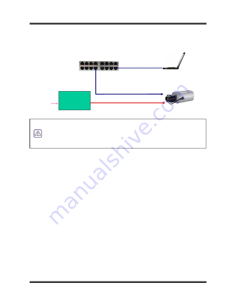
If you have standard power connect the network camera and PC as illustrated in Figure 
2.6


Figure 2-6. Connecting Network camera and PC using AC Adaptor 


Install “IP installer” and “XNET-NVR” on your PC 

Detailed  information  for  installing  these  software  can  be  found  in 

[IP-Installer  User’s 

Guide]

 and 

[XNET-NVR User’s Guide]

 respectively. 


Assign IP address to XNET/XNET-Wireless using IP installer


Identify  the  type  of  the  network  environment  and  set  up  IP  address.  Detailed  process  of 
setting up IP address can be found in [IP-Installer User‟s Guide]. If network type is xDSL or 
Cable modem you need supplementary information provided by your ISP. 


Connect to the XNET in Administrative Mode for initial parameter set-up


All  parameters  are  set  to  factory  default  state  when  XNET/XNET-Wireless  is  delivered.  You 
are  asked  to  configure  the  system  for  your  environment  in  administration  mode.  Detailed 
information  of  using  administration  mode  can  be  found  in 

[5.  Configuring  XNET/XNET-

Wireless  in  Administrative  Mode]

.  Among  the  parameters,  the  parameters  in  the 

following table should be set-up with proper values. Detailed information for the parameters 
in  Administrative  Mode  is  found  in 

[5.  Configuring  XNET/XNET-Wireless  in 

Administrative Mode]


[Note]: Set-up values are preserved even the power is turned off. 


The table below shows the Administrator Mode‟s parameters list. 

XNET 

DC In 

AC Adaptor 

AC In 

LAN Hub 

100BaseT 

PC 

The XNET Series does not support standard PoE. Do not connect the network 
camera  directly  to  a  hub  supporting  standard  PoE.  We  assume  no 
responsibility  for  the  damages  caused  by  use  of  standard  PoE  device  with 
this product. 


Summary of Contents for Network Box Camera

Page 1: ...XNET Network Box Camera User s Guide 1 of 47 XNET Network Box Camera User s Guide Ver 1 0 070918...

Page 2: ...sed in accordance with the instructions may cause harmful interference to radio communications However there is no guarantee that interference will not occur in a particular installation If this equip...

Page 3: ...nstaller 14 4 1 Main window of IP Installer 14 5 Configuring XNET in Administrative Mode 15 5 1 Log On 15 5 2 Basic Setup 16 5 3 Network Configuration 19 5 4 Wireless Configuration XNET Wireless Only...

Page 4: ...with standard Ethernet interface while the wireless XNET series is offered with embedded WiFi solution 1 2 Features of XNET 1 channel synchronized real time Video Audio streaming MPEG 4 video ADPCM a...

Page 5: ...nts Description Remarks XNET XNET Wireless XNET XNET Wireless Network Camera Power adapter Input 100 250V 50 60Hz Output 12V 3 33A Standard Power AC power cable AC 250V 10A 16A Antenna XNET Wireless o...

Page 6: ...s basically delivered without Lens assembly Standard C or CS type lens can be accommodated into XNET XNET Wireless Either DC Iris lens or Non DC Iris lens can be used with XNET XNET Wireless Auto Iris...

Page 7: ...left and LINE OUT right LINE OUT Connect speakers with built in amplifier Audio from remote site is output through Line out in bi directional audio mode Use the standard stereo earphone jack for the...

Page 8: ...ut of XNET XNET Wireless Do not apply power through this power input when power is applied through LAN cable using proprietary PoE RS 485 and ALARM IN OUT Used for connecting P T device sensor and ala...

Page 9: ...t Supported O S Windows 2000 Professional Windows XP Professional Windows XP Home Edition 2 5 Quick Installation Guide Brief information for rapid installation is provided in this section For more det...

Page 10: ...itial parameter set up All parameters are set to factory default state when XNET XNET Wireless is delivered You are asked to configure the system for your environment in administration mode Detailed i...

Page 11: ...put changed values for corresponding fields Do not disclose these values to others and memorize these values Default value Username root Password dw2001 Current Time Input correct time in this field D...

Page 12: ...ator mode for the first time enter the username default root and password default dw2001 3 Connecting XNET XNET Wireless to the Network XNET XNET Wireless supports LAN xDSL and Cable modem It also sup...

Page 13: ...device to forward packet data with unique port number RTSP and HTTP to unique internal IP address local IP address If you only plan to access multiple units from within a local area network you do no...

Page 14: ...for the initial connection to IP video products can be assigned by IP Installer Once the basic parameters are assigned and the initial connection is When a static IP address is assigned to the xDSL o...

Page 15: ...de will explain accessing by IE and XNET NVR only Please refer to the XNVR user s guide in the supplied CD for using XNET XNVR 5 1 1 Log on from Internet Explorer The URL of the XNET administrative mo...

Page 16: ...Basic Setup page of Administrative Mode If you have changed the username and password of the Administrator you must log on with the changed username and password If you forget the user name and passw...

Page 17: ...a language of your choice English Korean Chinese Japanese Spanish Italian Portuguese are available System Name Logical name of the XNET It is same as the one set up by IP installer You can reassign t...

Page 18: ...ate Assign number of video frames to be transmitted for each second You can improve picture quality by lowering frame rate for the same bandwidth Video rate Assign bandwidth for transmitting video dat...

Page 19: ...de 19 of 47 5 3 Network Configuration Setup the network parameters appropriately in accordance with your network environment Many of the parameters in this page are same as those set up by IP Installe...

Page 20: ...guide for Host name and domain for Cable Modem Clone MAC Refer to IP installer user s guide for Clone MAC Port Change Each port should have a number below 65 535 RTSP The RTSP port is used for transmi...

Page 21: ...and Directory of FTP server to send data in case of alarm Default FTP port number is 21 FTP Server Setup You can register the network camera to the Management Server DDNS Server for name service to yo...

Page 22: ...cted Ethernet interface is used instead of wireless LAN interface WLAN Radio Select the mode of Wireless Radio SSID Enter the ID of the wireless LAN access point to be connected when wireless LAN inte...

Page 23: ...of the access point is shown Current Channel Indicates the channel number of present connection Signal Strength Indicates the strength of the received signal Link Quality Indicates the quality of Link...

Page 24: ...ns Any lens having C or CS mount type can be installed on XNET A C CS adaptor is packaged with XNET for accommodating CS type lens Confirm whether your lens is Non DC IRIS or DC IRIS lens before your...

Page 25: ...r speed is set to 1 100 sec for NTSC camera while it is set to 1 120 for PAL camera to synchronize the shutter speed to AC current The default value is OFF Note Make sure that you apply this mode only...

Page 26: ...ID and password of users and also assign different attributes for each user Figure 5 7 User Admin Time Setup Field Button Sub Field Button Description User Administration Administrator Username Admin...

Page 27: ...e format user id A BA P A audio B bi directional audio P ptz Pan Tilt not used for this model You can delete specific user by clicking the DELETE button Authentication for Viewing YES SAVE If you want...

Page 28: ...s you can assign time server by filling in Specific Time Server field Synchronize With this Computer Time Synchronize the time with the time of the PC Set Manually Set the time manually Fill in the fi...

Page 29: ...There are two types of sensors which are Normal Open and Normal Close Name Input logical name for the sensor Video Capture Condition It sets the condition of video transmission via FTP or E mail The X...

Page 30: ...FTP Server Refer to Section 5 3 If the FTP server is not properly assigned in Network Configuration mode XNET XNET Wireless ignores the video transmission by FTP SAVE Save the setup parameters When t...

Page 31: ...relay contact OFF Off the alarm output Open the relay contact Sound Test Used for audio voice testing Alarm Device Active Condition Setup the condition of activating alarm device Select sensor or mot...

Page 32: ...etection regions Up to 3 regions can be defined Figure 5 11 Motion Region Setup Field Button Sub Field Button Description Channel Selection Not applicable Channel Sensitivity Set the sensitivity in mo...

Page 33: ...detection zone will be indicated with corresponding colors Legend of the color 3 Region 1 red Region 2 green Region3 blue START Enable selection of rectangular zone start END Enable selection of recta...

Page 34: ...Setup Field Button Sub Field Button Description Channel Selection Not applicable PTZ Model Selection Choose the PT model Delete Button Press this button to delete the setup of PT PTZ Device ID Your P...

Page 35: ...me as the PT device allows Panning Limitation SET Set the present position as left or right panning limitation Panning Limitation TEST Test the panning limitation which was set previously Preset Posit...

Page 36: ...eck at the box at the left of the Enable data encryption then check at the proper check boxes at the left of Video and Audio After the selection click on SAVE button beneath the Video and Audio check...

Page 37: ...Download Key value to your PC The key values can be downloaded and stored as a file to your PC for reference when you make connection When encryption is enabled the PC client program will ask for par...

Page 38: ...eld Button Sub Field Button Description Automatic Upgrade Automatic upgrade is a feature that enables network camera to upgrade to newly released system software by automatically connecting to upgrade...

Page 39: ...6 4 How To Upgrade Your XNET XNET Wireless System Factory Default Setting Re initialize the network camera to factory default state By checking on a Radio button Except Network Configuration you can p...

Page 40: ...User s Guide 40 of 47 5 13 Status Report It shows you system records since the system started You can check the problems as well as the versions and event status of the whole system and each module Fi...

Page 41: ...sensors motion sensors heat smoke sensors magnetic sensor etc ALARM OUT is used for connecting alerting device such as loud speaker flashing light etc Figure 6 1 ALARM IN ALARM OUT Connector 6 1 1 AL...

Page 42: ...T A Relay output is provided for connecting alarm devices or for remote on off devices such as light control Relay circuits are normal open and circuits are closed upon alarm output or remote on The r...

Page 43: ...pen CollectorType Photo Coupler 6 1 3 2 Connection of Relay Alarm Out Device Relay1 Power Supply 1 30 VDC AC 1A Relay1 Relay Switch Power Supply 1V 30VDC AC 1A Optional Relay Switch Alarm Out Device P...

Page 44: ...properly connected 6 2 2 After Successfully Connecting to the XNET XNET Wireless Video movement is slow In Basic Setup of Admin Mode lower the Quality High quality means more data You can also set th...

Page 45: ...XNET Wireless is designed to be connected through internet explorer too For connection to XNET XNET Wireless using internet explorer type in IP address or host address in the address input field of t...

Page 46: ...creen by 180 degree Connect to XNET XNET Wireless Stop the connection Contrast Brightness and Volume adjustment Check the box to mute the audio Adjust the size of the screen Normal x1 Twice x2 Half 1...

Page 47: ...ck Browse to find the files you want to use for upgrade This will open a Choose file dialogue window The file extension is ief 4 When you ve found the file click Open This will select the file and clo...

Reviews: