

22
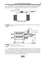
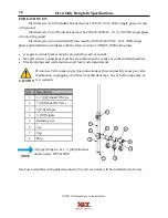
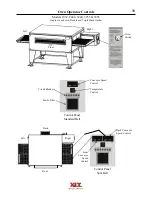
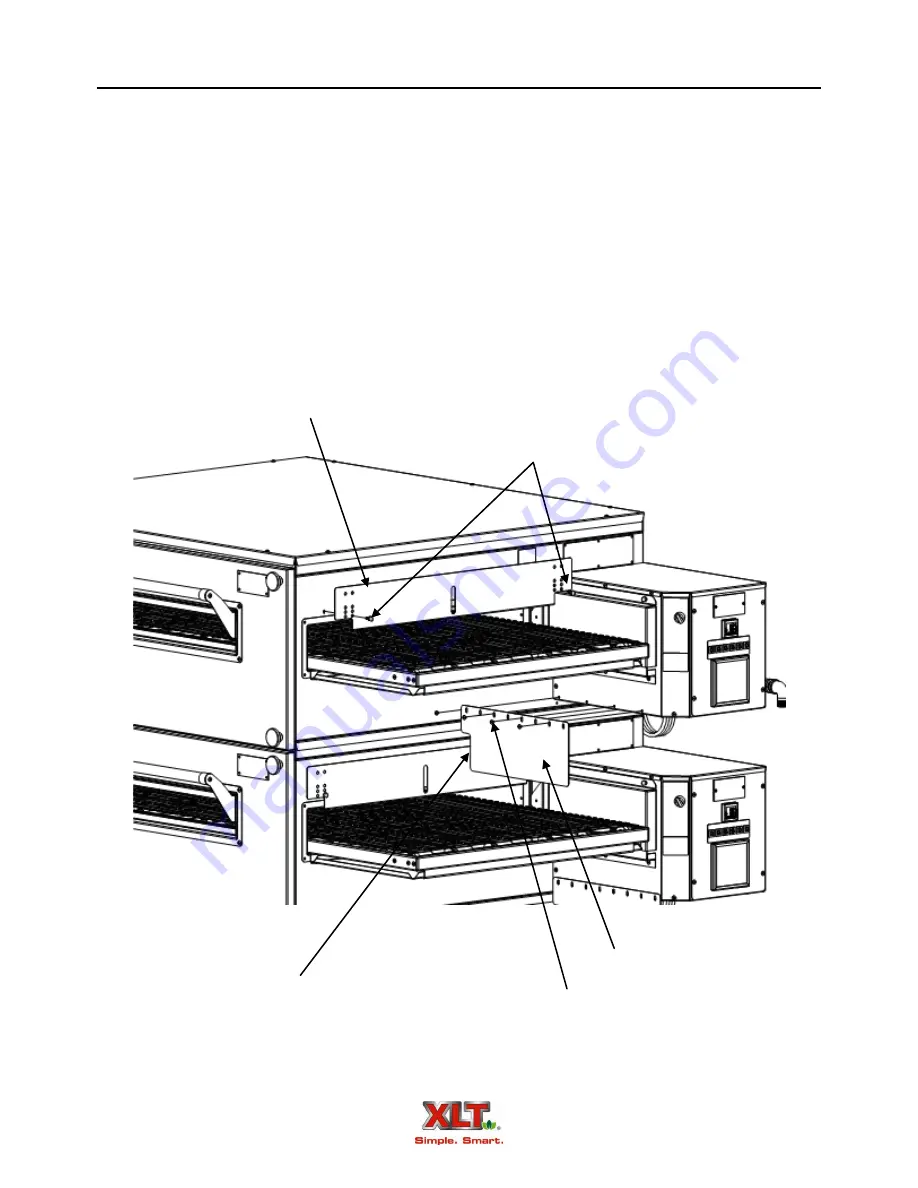
8. Reinstall the conveyor opening flaps in each oven deck. A series of holes in the flaps allow
adjustment for different heights of food product.
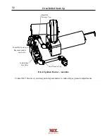
9. Control box heat shields need to be installed on any multi-deck installation. For xx70 models,
they are required on both ends. To install, remove the four (4) control box screws under the
conveyor. Place the panel with the notch towards the bake chamber. Line up the slots with the
existing holes and replace the screws.
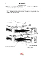
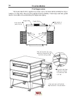
Oven Assembly
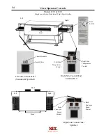
Conveyor Opening Flap
Thumb Screws
Lower Control Box Plate
Control Box Screws
Lower Control Box Plate Notch
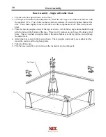
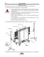
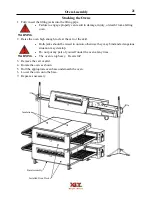
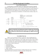
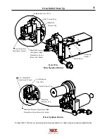
Stacking the Ovens
Summary of Contents for 1832-AE-B
Page 43: ...43 This page intentionally left blank ...
Page 88: ...This page intentionally left blank ...
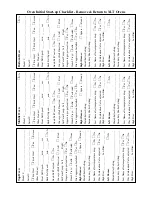
Page 95: ...95 Oven Schematic 1832 2440 3240 3255 3855 Square Burner Standard ...
Page 96: ...96 Oven Schematic 1832 2440 3240 3255 3855 Square Burner World ...
Page 97: ...97 Oven Schematic 1832 2440 3240 3255 3855 Round Burner Australia ...
Page 98: ...98 Oven Schematic 3270 3870 Square Burner Standard RH Control Box ...
Page 99: ...99 3270 3870 Square Burner Standard LH Control Box Oven Schematic ...
Page 100: ...100 Oven Schematic 3270 3870 Square Burner World RH Control Box ...
Page 101: ...101 Oven Schematic 3270 3870 Square Burner World LH Control Box ...
Page 102: ...102 3270 3870 Round Burner Australia LH Control Box Oven Schematic ...
Page 103: ...103 Oven Schematic 3270 3870 Round Burner Australia RH Control Box ...
Page 104: ...104 Hood Schematic Standard ...
Page 105: ...105 Hood Schematic World ...


