


25
Restraint
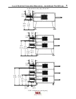
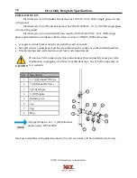
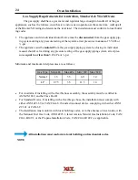
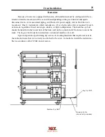
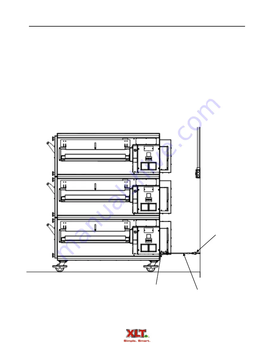
Because all ovens are equipped with casters, all installations must be configured with a re-
straint to limit the movement of the oven without depending on the gas connector and quick-
disconnect device or its associated piping, and the electric power supply cord to limit the oven
movement. One (1) restraint kit, which includes two (2) eye bolts and a cable, is required for each
oven stack, regardless if used on a single, double, or triple configuration. The machine eye bolt
should be installed in the lowest hole of the back wall on the control end of the lowest oven in the
stack. The lag eye bolt must be installed into a structural member of a wall.
Upon completion of performing any service or cleaning functions that require removal of
the restraint, insure that it is correctly re-attached to the oven. In Australia, install the restraint ca-
ble in accordance with AS 5601, latest version.
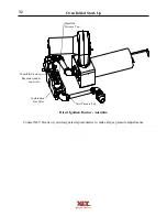
Oven Installation
Machine Eye Bolt
Restraint Cable
(shown fully extended)
Lag Eye Bolt
Summary of Contents for 1832-AE-B
Page 43: ...43 This page intentionally left blank ...
Page 88: ...This page intentionally left blank ...
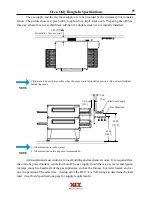
Page 95: ...95 Oven Schematic 1832 2440 3240 3255 3855 Square Burner Standard ...
Page 96: ...96 Oven Schematic 1832 2440 3240 3255 3855 Square Burner World ...
Page 97: ...97 Oven Schematic 1832 2440 3240 3255 3855 Round Burner Australia ...
Page 98: ...98 Oven Schematic 3270 3870 Square Burner Standard RH Control Box ...
Page 99: ...99 3270 3870 Square Burner Standard LH Control Box Oven Schematic ...
Page 100: ...100 Oven Schematic 3270 3870 Square Burner World RH Control Box ...
Page 101: ...101 Oven Schematic 3270 3870 Square Burner World LH Control Box ...
Page 102: ...102 3270 3870 Round Burner Australia LH Control Box Oven Schematic ...
Page 103: ...103 Oven Schematic 3270 3870 Round Burner Australia RH Control Box ...
Page 104: ...104 Hood Schematic Standard ...
Page 105: ...105 Hood Schematic World ...


