


Operation Manual 37107F
MFR 3 - Multi Function Relay
© Woodward
Page 143/165
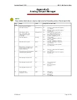
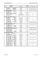
1)
Note to parameter 1 and 2:
The analog output is calculated according to the displayed real power without the
engineering unit of measure "kW" or "MW". The number of displayed digits is valid. Example: 20 mA corres-
ponds to "200".
20 mA will be output at the following display: 200 kW or 20.0 MW
10 mA will be output at the following display: 100 kW or 10.0 MW
The control unit automatically switches from "kW" to "MW" when the primary transformer real power of
3,000 kW is exceeded:
I
gen prim
× V
gen prim
×
√
3
≥
3,000 kW.
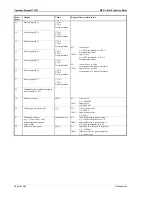
The description 0 % corresponds to the minimum input of 4 mA or 0 mA; the description 100 % corresponds to
the maximum input of 20 mA. The values can be entered with or without a leading sign (see parameter 1).
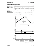
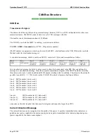
Definition of power factor scaling:
According to the scaling of the analog output, the power factor can be out-
put within the range from capacitive values ranging from c0.00 to unity power factor = 1 to inductive values up
to i0.00.
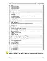
Scalable range (0 to 20 mA)
eg. c0.70 to 1.00 to i0.70
Power factor cosphi = 1.00
c 0.00
Capacitive
(negative)
Lower distance
eg. 0030
Higher distance
eg. 0030
i 0.00
Inductive
(positive)
Figure 7–2: analog outputs – power factor scaling


