Operation Manual 37107F
MFR 3 - Multi Function Relay
Page 104/165
© Woodward
Example:
Initial conditions:
Rated voltage V
n
= 100 V
Configured value I
p
= 2.0*5 A = 10 A (rated current I
n
= 5 A)
Case 1 (monitored voltage V > 90% V
n
):
As long as the monitored voltage exceeds 90% of the rated voltage, the configured value will not be adjusted.
-> I
a
= I
p
Case 2 (monitored voltage V < 90% V
n
, but actual voltage V > knee curve setting):
If the monitored voltage falls below 90% of the rated voltage, the configured value is adjusted proportionally
with the ratio of monitored and rated voltage.
-> I
a
= (V/V
n
) * I
p
Case 3 (monitored voltage V < knee curve setting):
If the monitored voltage falls below the percentage value of the rated voltage configured by the knee curve
setting (Parameter 146), the configured value is adjusted to the proportional value at the knee curve setting.
-> I
a
= {(knee point setting in [%])/100} * I
p
If the knee curve setting is configured to 20% for example and the monitored voltage is lower than 20% of the
rated voltage, the adjusted value I
a
falls not below 20% of the configured value I
p
.
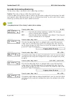
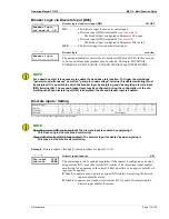
Parameter
145
Inv.time ov.cur.
V-restr. ON
Voltage restraint time-overcurrent
ON/OFF
ON
................ Inverse time-overcurrent monitoring with voltage restraint is enabled.
The subsequent screens of this function are displayed.
OFF
.............. Inverse time-overcurrent monitoring is not performed. The subse-
quent screens of this function are not displayed.
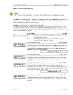
Parameter
146
Inv.time ov.curr
knee curve U>00%
Voltage restraint time-overcurrent
10 to 90 %
The threshold limit for the voltage is defined in this parameter. The knee of the
curve describes the lower limit of the threshold value lowering, i.e. the trip current
belonging to this limit remains valid and will not be lowered further in case of an
additional voltage drop.
Tripping of alarm class 3


