


1-6
Chapter 1: Introduction and Features
November 2007
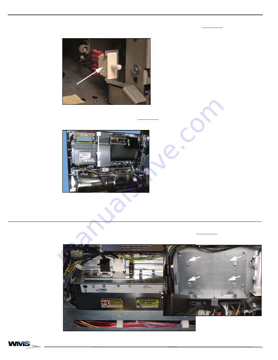
Door Switches
The Main Door switch confirms that the door is closed properly and places the game into play mode.
The switch is located on the right side of the cabinet, above the shelf,
.
Figure 1-6 Main Door Switch above LCD Shelf.
The Belly Door switch confirms that the Belly Door is closed. The Belly Door Switch is located in the
center of the inside of the Belly Door,
(A).
Figure 1-7 Belly Door Switch in center of inside of Belly Door.
Both switches are accessible with one hand, enabling easy maintenance and testing of game
functionality.
CPU Enclosure
The CPU Enclosure protects the CPU Board and is completely removable from the game. Four
square tabs on the back of the enclosure seat the CPU Enclosure,
.
Figure 1-8 CPU Enclosure installed (left) and four mounting tabs (right).
A
Summary of Contents for Bluebird Series
Page 2: ......
Page 12: ...4 List of Figures November 2007 ...
Page 16: ...4 About this Guide General Information October 2007 ...
Page 101: ...5 13 Chapter 5 Exploded Views Block Diagram for BBU AC Power Distribution ...
Page 102: ...5 14 Chapter 5 Exploded Views Block Diagram for BBU Bulkhead with CPU NXT ...
Page 103: ...5 15 Chapter 5 Exploded Views Block Diagram for BBU Bulkhead with CPU NXT ...
Page 104: ......


