background image

Safety


2

Translation of the original operation manual 

9

•303_208176_1004_en•ski

Danger to the unit


A change of the mixing ratio may have the consequence of the change of the pres-

sure ratio and a required change of the maximum allowed compressed air pressure. 

The installed safety valve must be changed. In this case you get from 

 an 

exchangeable nameplate with the new now valid data of the 2K-unit.
We recommend strongly to consult 

 in this case.


The unit should never be operated without safety valve!

Should  the  safety  valve  need  replacing,  please  see  the  machine  card  for  its  order 

number.

With new safety valves take care that these are set and leaded at the maximum allow-

able inlet compressed air pressure of the 

 DUOMIX (see nameplate/machine 

chart) corresponding to the mixing ratio.


During operation, ensure that sufficient feed of material is available to the pump in 

order to avoid heating due to friction, caused when the material pump runs dry.
Observe closely:


no empty feed containers may be present during operation.


the suction system may not be clogged, buckled or defect in any other way.


if the unit stops processing material, shut it down immediately.


The maximum operating pressures are to be adhered to in principle for all 


parts (eg. pump, heater, hoses, gun, safety valve).
By differing allowable operating pressures, the lowest value is always the maximum 

allowable operating pressure for the entire system.

General example:

Pump 

up to 420 bar

Material hose 

up to 600 bar

Spraying gun 

up to 500 bar

The maximum allowable operating pressure for this example would be 420 bar.

Danger through explosion


Never spray solvents or materials containing solvents into a narrow-necked can or 

barrels with bung hole!

DANGER OF EXPLOSION!


Please, always use an open container. Due to possible electrostatic charges, it is 

imperative to ensure that the spraying gun has contact to the container walls when 

working with metal containers.
It is possible for a static charge to occur due to the high flow speeds during the airless 

spraying procedure. Static charges can lead to fire and explosions.

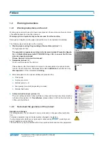
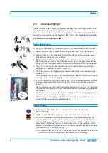
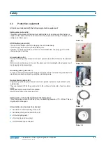
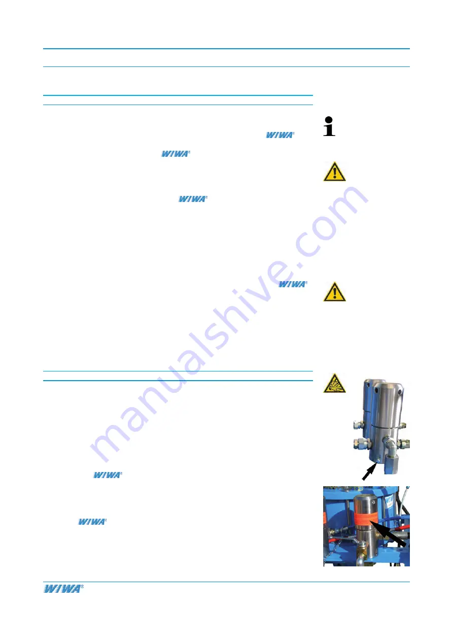
The equipment must, therefore, always be appropriately grounded (picture 2.3).

The original 

 DUOMIX is fitted with a ground cable as standard. If lost or 

defective, please, order an immediate replacement (for order no. please refer to the 

machine card).


Never use this equipment outdoors during a thunderstorm.


Due to electrostatic charges, only conductive material hoses should be used. All 

original 

 material hoses are conductive and compatible with our equipment. 

The maximum admissible working pressure on the hoses must correspond to the 

maximum operating pressure of the unit.

Picture 2.3


Summary of Contents for Duomix 333

Page 1: ...Blvd Chesapeake VA 23323 USA Tel 1 757 436 2223 Fax 1 757 436 2103 Tel Toll Free 1 866 661 2139 E mail sales wiwalp com Internet www wiwa com WIWA Taicang Co Ltd Add No 87 East Suzhou Rd Taicang city...

Page 2: ...tary authority Heidrun Wagner Turczak Tel 06441 609 0 The manufacturer commits to electronic transmission of the equipment specific docu mentation for the incomplete units to individual national autho...

Page 3: ...of the machine 14 3 2 Danger arising from the equipment 14 3 3 Machine surroundings 15 3 4 Transport 15 3 5 Installation site 16 3 6 Component description 17 3 7 Diagram of the settings of the mixer...

Page 4: ...500 Kap 2 29 and the guidelines covering fluid sprayers Richtlinien f r Fl ssigkeitsstrahler ZH1 406 from the German Employer s Liability Insurance Association are to be observed without fail To ensu...

Page 5: ...e information located on the nameplate corresponds to data found on the machine card We request immediate notification should there be any discrepancies or if the nameplate is missing More nameplates...

Page 6: ...u should adhere to Please read and observe the guidelines valid for your country In Germany the Richtlinien f r Fl ssigkeitsstrahler Guidelines for fluid spray ers published by Hauptverband der Gewerb...

Page 7: ...operation manual of the optional accessory equipment WEAR PROTECTIVE GLOVES Wear protective gloves with lower arm protection to avoid burn injuries The warnings must be adhered to USE EAR PLUGS For h...

Page 8: ...icture 2 2 as well as the air pressure regulator of the main pump must be closed If the material being used clogs or clumps within the unit remnant pressure may still exist despite depressurization ef...

Page 9: ...all parts eg pump heater hoses gun safety valve By differing allowable operating pressures the lowest value is always the maximum allowable operating pressure for the entire system General example Pum...

Page 10: ...eport any changes in the machine which might affect its safety to the manager as he must ensure that the machine is functional The responsibilities for the different activities on the system must be l...

Page 11: ...unit the whole system including the feed pumps must be stopped and depressurized Grounding cable picture 2 7 In order to avoid an electrostatic charge being built the 2K unit must be grounded to an el...

Page 12: ...and repair of the machine Activity Personnel Qualification Adjusting work trained operator Servicing work trained operator Cleaning work trained operator Maintenance work personnel trained by customer...

Page 13: ...e to keep the gun in contact with the container Damaged parts must be replaced immediately Injury Should an injury occur through contact with liquid spray we recommend a doctor be called immediately I...

Page 14: ...cident prevention It left the factory in perfect condition and warrants a high level of safety However the following dangers exist if operated incorrectly or used inappropriately to life and limb of o...

Page 15: ...e shown in the machine card The unit should only be suspended using the foreseen lifting holes Keep care to have free hanging ropes if necessary use yoke suspension The length of the lifting ropes sho...

Page 16: ...e to prevent damage to health and property Observe the manufacturer s processing instructions at all times Despite the fact that no legal regulations exist covering the low fog airless spraying method...

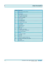
Page 17: ...n of the original operation manual 17 303_208176_1004_en ski 3 6 Component description 1 1 1 1 2 1 3 1 4 1 5 1 6 2 2 1 2 2 2 3 3 4 5 6 6 1 10 B 10 1 10 A 10 1 9 B 9 A 10 2 B 10 2 A 12 B 12 A 11 8 B 8...

Page 18: ...6 stroke counter 2 air maintenance unit 2 1 air cut off ball valve 2 2 air regulator of main pump 2 3 de icing modul 3 contact gauge 4 high pressure filter 5 dispensing unit 6 flush pump 6 1 air regul...

Page 19: ...ranslation of the original operation manual 19 303_208176_1004_en ski Remote mixer 13 2 13 3 13 1 Position Description 13 1 lever CIRCULATION 13 2 lever SPRAY 13 3 lever for separate flushing of the A...

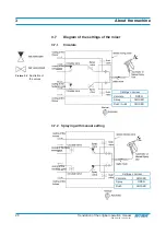
Page 20: ...208176_1004_en ski 3 7 Diagram of the settings of the mixer 3 7 1 Circulate Settings on mixer Circulate OPEN Spray CLOSED Flush A B CLOSED 3 7 2 Spraying with manual setting Settings on mixer Circulat...

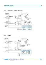
Page 21: ...original operation manual 21 303_208176_1004_en ski 3 7 3 Spraying with automatic monitoring Settings on mixer Circulate CLOSED Spray OPEN Flush A B CLOSED 3 7 4 Flushing Settings of the mixer Circul...

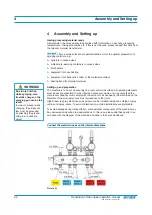
Page 22: ...urface All operating elements must be easily accessible In order that the necessary volume of air is guaranteed the compressor capacity must comply with the amount of air needed by the machine and the...

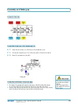
Page 23: ...e air pressure connection Picture 4 2 Connect the fluid heater on the power supply The heater is equipped with a permanent power connection cable without plug For versions without cable and cable conn...

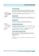
Page 24: ...into the oiler of the air maintenance unit and adjust it In very cold working conditions you may add some anti freeze to avoid icing Drop metering of Fog Oiler picture 4 2 Let the equipment run slowly...

Page 25: ...e to adapt the pressure to get the desired result All position numbers found in this chapter apply to the specification in the chapter 3 6 Component description Task Cleaning the whole material circui...

Page 26: ...pos 13 1 to OPEN Make sure that the air regulator pos 2 2 on the main pump is set to 0 bar to insure that the unit can start from a complete stop Open the shut off pos 2 1 ball valve on the maintenan...

Page 27: ...RCULATE pos 13 1 to CLOSED Unlock the spray gun Spray into an open container the rest contaminated thinner which is in the system until clean thinner appears Lock the spray gun when finished Turn back...

Page 28: ...ARNING Parts of the hand can be crushed or cut while lowering the drum cover onto the container edge Never hold parts of the body finger etc in the area of the container edge and drum cover Make sure...

Page 29: ...up the air for the de icing module Please refer to the separate user s handbook of the fluid heater Allow the rest of the thinner which is in the system to flow via the return hoses pos 9 into an empt...

Page 30: ...e lever on the external mixer SPRAY pos 13 2 to OPEN FLUSH pos 13 3 A B to CLOSED CIRCULATE pos 13 1 to CLOSED Now slowly set the air regulator pos 2 2 of the main pump to the desired spraying pressur...

Page 31: ...his changeover is absolutely necessary as otherwise the system will not be moni tored The AUTOMATIC position ensures optimum monitoring of the equipment and avoids wrong proportioning Result The compl...

Page 32: ...coating thicknesses Spraying Coating Hold the spray gun at a right angle 90 to the surface of the object being coated If the gun is held at any other angle the coating will be applied uneven and patc...

Page 33: ...sk Preparation for the spraying Initial situation The unit is already set up and the job is restarted after a work interruption The system is filled with material up to the mixer refer to chapter Init...

Page 34: ...AUTOMATIC Result You can proceed with normal operation of the unit 6 3 Pause in work and end of work CAUTION Apply the spray gun safety catch if stopping work even for a few minutes Static charges can...

Page 35: ...to MANUAL Trigger gun shortly to pressure release the equipment Settings on the mixer flush Turn lever on the external mixer SPRAY lever pos 13 2 to CLOSED FLUSH pos 13 3 A B to OPEN CIRCULATE lever p...

Page 36: ...n of the material being processed and the duration of the pause it may be wise to stop the work on the machine completely and start it later again see chapter Job commencement Please refer to the mate...

Page 37: ...or a pause or finishing work with the machine All crucial areas on the machine were flushed with thinner 6 4 Material Change Clean System thoroughly see chapter Complete Cleaning We recommend disassem...

Page 38: ...from the material container to the mixer gets flushed All equipment for preparation of the material heaters and or agitators are turned off and they are disconnected from the power supply When thinne...

Page 39: ...commended by the material manufacturer WARNING Parts of the hand can be crushed or cut while lowering the drum cover onto the container edge Never hold parts of the body finger etc in the area of the...

Page 40: ...eturn hoses in the thinner Let the equipment circulate and pump for about 20 minutes NOTE Please take absolute care to separate both components Base and Hardener during cleaning so therefore ensure NE...

Page 41: ...dry Settings on the mixer circulate CLOSED Turn levers on the external mixer SPRAY pos 13 2 to CLOSED FLUSH pos 13 3 A B to CLOSED CIRCULATE pos 13 1 to CLOSED Turn the air regulator pos 2 2 of the ma...

Page 42: ...nts conditions 1 2 days period Clean suction filters refer to chapter 8 2 2 and high pressure filters refer to chapter 8 2 1 before start to work in the morning Weekly period Check pneumatic oiler of...

Page 43: ...Clean the filter insert and re install it Clean the thread of the high pressure filter cap and put some grease on it Close the high pressure filter securely Open the low pressure ball valves in front...

Page 44: ...of base increases Bottom valve of the hardener pump is defective Remove and clean the bottom valve Replace defective ball or valve plate 4 When the dosing pump is on the upstroke the hardener pump doe...

Page 45: ...er return hoses are clogged Clean high pressure filter 11 When draining pressure of hard ener remains Pressure of base drops Drain valve of hardener does not open Return hoses are clogged High pressur...

Page 46: ...o SPRAY and when opening the spray gun the pressure of one component rises and the other one falls One automatic valve does not open Check valves and repair 18 When switching from SPRAY to FLUSH the f...

Page 47: ...25 The contact gauge shows no pres sure or only to a certain value The unit is supplied with air The black indicator is fixed on one value and is not moving Pressure gauge is defective Oil is leaking...

Page 48: ...erial pump are worn Replace packings and gaskets 31 A fluid heater does not operate Electrical power supply is cut off Ambient temperature is below 5 8 C 9 14 F Technical defect in the fluid heater Co...

Page 49: ...nd or repairs see for specifications in the spare parts list Special tools Picture 10 1 Key for opening of the high pressure filter Attention The high pressure filter should only be opened when sys te...

Page 50: ...he operating personnel Make Model Year of Construction Order Number The training was conducted by the following designated person Foreman or responsible Superior Name Department The person trained has...

Reviews: