Safety
2
Translation of the original operation manual
11
11
•303_208176_1004_en•ski
2.4
Protective equipment
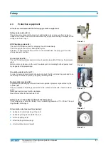
All units are delivered with the following protective equipment:
Safety valve (picture 2.4)
The safety valve prevents the maximum admissible entry air pressure from being ex-
ceeded. In the event that the fixed maximum entry air pressure setting is surpassed, the
safety valve blows open.
STOP-Button (picture 2.5)
The red STOP-Button allows for stopping the unit immediately.
The air supply to the motor is interrupted by this.
Attention: To depressurize the unit also on the material side, the spray gun* must be
shortly opened a last time.
Air lock (picture 2.6)
The tap for locking compressed air makes it possible to switch off the machine immedi-
ately.
Before work can be done on the unit, the whole system including the feed pumps must
be stopped and depressurized.
Grounding cable (picture 2.7)
In order to avoid an electrostatic charge being built, the 2K-unit must be grounded to an
electrically conductive object by using the grounding cable.
Rupture disks (picture 2.8)
Significantly exceeding the allowed maximum operation pressure is prevented by the
rupture disks.
They are located in the fittings connected to the outbound fluid ports of each material
pump.
Damaged rupture disks must be replaced.
See order number in the machine chart.
Safety valve on the outlet manifold of the feed pumps
This safety valve is set at the factory for an a operating pressure of 70 - 80 bar. This set-
ting should not changed.
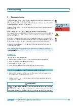
All protection devices must be checked:
➤
before each commissioning of the unit!
➤
before beginning work on/with the unit!
➤
after all aligning work!
➤
after cleaning and servicing!
➤
after maintenance and repair!
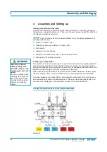
Picture 2.4
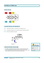
Picture 2.5
Picture 2.6
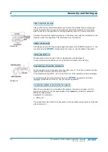
Picture 2.7
Picture 2.8


