


1%: < 33 ms
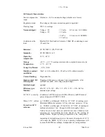
DC Output Characteristics:
Sense compensation
range:
Limited to < 10V or nominal voltage (whichever is lower).
Regulation mode:
The voltage at the sense connection point is regulated.
Floating range:
500 V test voltage
Noise and ripple:
Voltage < 8 V
Voltage > 8 V
< 10 mV
PP
< 15 mV
PP
(0.5 m wire, 0–20 MHz)
< 3 mV
PP
< 1.5 mV
RMS
(10 m wire, 0-300 MHz)
Conditions at the
load:
Parallel (X) 330µF and 1µF ceramic, 100nF HF- conducting to case
(Y) each line
Emission:
CE EN 50081-1 (EN 55 022-B)
Immunity:
CE EN 50082-1 or 2
Operating
temperature:
10 °C – 40 °C
Storage
Temperature:
- 30 °C - + 85 °C (cooling water must be completely removed, else
+3 °C - +85 °C)
Temp.- Coefficient:
< 0.2% / 10K
Stability (constant
conditions)
<5mV or 0.1% within 24 h, <25mV or 0.3% within 6 months
Current limiting:
Programmable
Status control / DC
Off (trip off):
Tripping global, group- or channel wise programmable (after
overload, overheat , overvoltage, undervoltage)
Interlock input:
optional
Efficiency (per
Module):
65% 2V/ -81% >5V/ -85% >7V -87% >12V/ -90% >48V at
nominal input voltage
M T B F, cooled by:
Water, 30°C inflow:
Forced Air, 30°C
entrance:
Conditions: 3kW DC output with 80% efficiency (600W internal
power dissipation: WORST CASE)
ca. 120,000 h , put through > 50l/h for <10°C DT of cooling water.
Minimum differential pressure >0.5 bar, abs. max. pressure <15 bar
ca. 90,000 h , put through > 153m3/h for <15°C DT of cooling air,
ambient air pressure 1 bar. Adequate airflow is roughly 1,4m/s.
Values for air cooled units are valid for new ones. Abrasive dust,
corrosion, etc. can limiting the heat transfer to the cooling air
during lifetime. Higher operating temperature is the consequence.
Increasing of internal temperature at the most critical points of 10°C
will reduce the MTBF by 50% Lower operating temperatures will
increase the MTBF accordingly, independent of cooling medium.
8. June 2010
19
*00679.A1