


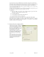


3.3.1 Read Power Supply Data From File Dialog
This dialog can be
used to copy a XML
configuration file
from disk to the
PL512.
It is possible to copy
each configuration file
channel to its
corresponding power
supply channel (e.g.
U0 → U0, U1 →
U1, ...) or to copy one
configuration file
channel to multiple power supply channels.
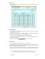
3.3.2 Output Configuration Dialog
This dialog allows the detailed configuration of each power supply channel.
The
Measurement
group shows the measured sense voltage, terminal voltage and current.
The sense voltage is the voltage at the sense lines, which are connected to the load. Terminal
voltage means the voltage at the terminals of the PL512.
Depending on the used modules, an analog or digital value of the most critical point of the
power module is displayed.
The power of the load and the output power of the module are calculated values.
In the
Nominal Values
group
the nominal values of the
output voltage, the maximum
current which the power
supply will source before it
switches into constant-
current mode, and the
voltage rise and fall rates are
entered.
If the
No Ramp at Switch Off
check box is checked, the
Ramp Down
value is only
used if the nominal voltage is
changed. If the voltage is set
to 0, the channel ramps down
to zero and than switches off.
But using the
OFF
button to
switch off cuts off the output
voltage immediately.
The voltage regulation
parameters can be modified
with
the
Moderate
Regulation
check box. If
unchecked, the standard (PI)
regulator is used. This is the
fastest regulation, but may
start ringing with wires to the
load longer than 1 meter.
8. June 2010
13
*00679.A1