


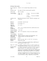


2.7 Channel-Wise Interlock Input (Optional)
The channel-wise interlock inputs are provided to force a dedicated output to be switched
off.
DSUB25 female
Pin Signal
Comment
1
Interlock U0 +
14
Interlock U0 -
2
Interlock U1 +
15
Interlock U1 -
3
Interlock U2 +
16
Interlock U2 -
4
Interlock U3 +
17
Interlock U3 -
5
Interlock U4 +
18
Interlock U4 -
6
Interlock U5 +
19
Interlock U5 -
7
Interlock U6 +
20
Interlock U6 -
8
Interlock U7 +
21
Interlock U7 -
9
Interlock U8 +
22
Interlock U8 -
10
Interlock U9 +
23
Interlock U9 -
11
Interlock U10 +
24
Interlock U10 -
12
Interlock U11 +
25
Interlock U11 -
13
reserved
Table 5: Channel-Wise Interlock Connector Pin Assignment
Each interlock input is galvanically isolated (optocouplers). If a channel is interlocked, it is
not possible to switch it on.
Signal level:
interlocked:
-10 V ... +0.8 V
not interlocked:
+2.2 V ... +10 V (input impedance 1 kΩ + LED, so higher input
voltages can be used if an external resistor is implemented.)
8. June 2010
5
*00679.A1