


20
7. INITIAL OPERATION
NOTE:
OilSafe recommends an initial Re-Circulation (“Kidney-Loop”) of the fluid at the first fill. Refer to Re-Circulation
(“Kidney-Loop”) Cycle Time Guide in the
Data Tables section (page 35)
for approximate run times to complete
single pass filtration of each tank.
Re-Circulation (“Kidney-Loop”) Cycle
STEP 12.
Put the operating valves in the “Re-Circulate” configuration – (left “DOWN”, right “UP”).
STEP 13.
Run each filled Bulk Tank for the approximate times set out in the Re-Circulation (“Kidney-Loop”) Cycle Time Guide table in the Data Tables
section (page 35).
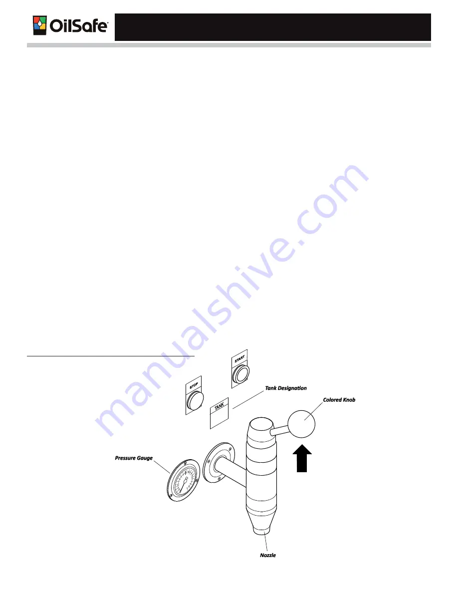
Dispenser Faucets
STEP 1.
Press START to start the pump.
STEP 2.
Place a clean fluid transfer or storage container under the tap (approximately 5 Gallon (10 Liter)) capacity.
STEP 3.
Lift up on the handle
See Figure 15 (standard faucet style illustrated)
.
STEP 4.
Release the handle and the flow will stop.
STEP 5.
Press STOP to stop the pump.
FIGURE 15:
Operating the Standard Dispensing Faucet
Summary of Contents for OilSafe Advanced Bulk System
Page 2: ......
Page 40: ...Advanced Bulk System 37 NOTES ...
Page 41: ...38 NOTES ...
Page 42: ......


