4-12
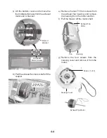
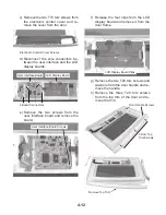
c) Remove the two T10 torx screws from
the electronic control cover and re-
move the cover from the door.
d) Disconnect the wire connectors be-
tween the user interface and the LCD
display boards.
e) Remove the two screws from the
user interface board and remove the
board.
f) Release the four clips from the LCD
display board and remove it from the
door frame.
g) Remove the two T20 torx screws and
washers from the door handle and re-
move the handle.
h) Remove the three T20 torx screws
from the top trim of the door and re-
move the trim.
Electronic Control Cover Screws
4 Board Connectors
User Interface Board LCD Display Board
User Interface Board Screws
LCD Display Board Clips
Door Handle Screws
3 Door Top
Trim Screws
Remove Top Trim
Summary of Contents for SPEEDCOOK GH6208 XR
Page 16: ...1 12 NOTES ...
Page 45: ...4 13 i Lift the door glass assembly off the door frame Remove Door Glass Door Glass Assembly ...
Page 76: ...5 10 NOTES ...
Page 82: ...6 6 NOTES ...
Page 92: ...8 6 NOTES ...
Page 93: ...8 7 NOTES ...
Page 94: ...8 8 NOTES ...
Page 96: ...CORPORATION ...


