38
connection dots from their default purple, green, and red; the color of the
logic connections from the default green; and change the grid background
and grid logo. Fortunately, you can also click the Default Crosspoint button
to return the settings to their defaults if you realize “customizing” the
crosspoint didn’t work out the way you thought.
The same holds true for the salvo crosspoint display. You can customize
it as well knowing there is a Default Salvo button that will return it back to
“stock” settings.
The Logger section is only shown when Enable Advanced Controls is
checked in the General section. The settings affect the System Log
operations and the Log tab. We recommend using the default settings, but
if a change is made, clicking Set applies the updated settings. Click Open
to open up the E2Logs folder which is where the various types of log files
(text files) can be viewed.
The Network section shows which NIC Navigator expects is connected
to PRE-IP devices. If no devices appear in the System Dock, look at the
NIC address shown here. If it is not correct, click Set… to open a dialog
box listing all of the NICs in the admin PC so the correct NIC (which should
be an address in the 192.168.87.0 subnet) can be set.
Log Tab
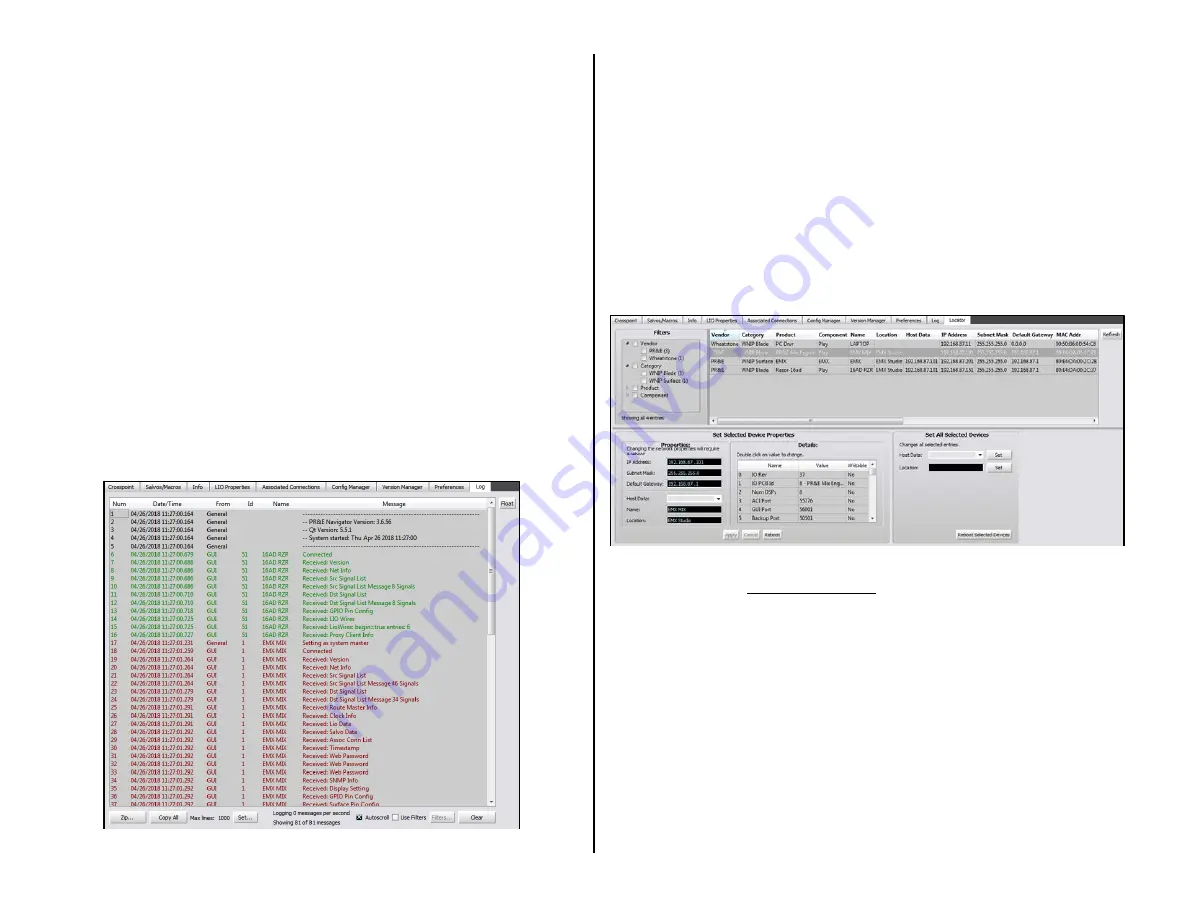
The Log tab (Figure 3-25) shows system messages sent by the PRE-IP
devices from the day and time Navigator was last started.
Figure 3-25 Log Tab
Its main purpose is as a troubleshooting tool, although you can get a
good sense of network communications by observing the log as the system
is in use.
The log saves a log file each day but the log is reset each time Navigator
is started, so if you want a complete log of operations we recommend
keeping Navigator running on at least one PC connected to your PRE-IP
network so you have an on-going log just in case you do run into problems
or unexpected operation.
Locator Tab
This tab (Figure 3-26) shows all of the Blades and Surfaces connected to
the network. Click Refresh to rescan the system and refresh the view. Note
that a similar view is obtained by clicking on System View but in that view
the Surfaces are shown under a separate tab from the Blades.
Figure 3-26 Locator Tab
Just as with the EMX Surface Setup Locator screen clicking on a device
lists its properties in the Set Selected Device Properties section where
the settings can be manually edited.
Blade Tabs
When any Blade: PR&E Mix Engine, Razor, M4IP-USB, or a PC with a
WNIP driver, is selected in the System Dock, the list of tabs change from
those shown while System is selected to show the Blade tabs. The Blade
tabs allow one to update the settings for that Blade’s input signals
(Sources tab); its output signals (Destinations tab, shown in Figure 3-27);
to save and/or print out a list of input and output connections (Wire Info
tab); to view and test the device’s logic connections (LIO Info tab); to
view and edit the Blade network settings (Blade Info); and to save or
restore that Blade’s settings (Config Manager tab). The M4IP-USB Blade
has two additional tabs: Silence Sense and Utility Mixer.
Summary of Contents for EMX
Page 4: ...4 ...


