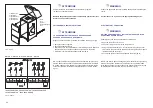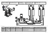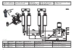
Fig.16 - Abb.16
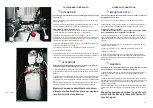
Fig.17 - Abb.17
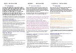
COLLEGAMENTO IDRAULICO
I
ATTENZIONE!
Un serraggio dei tubi troppo forte può danneggiare la sede conica
dei raccordi.
si può procedere con le operazioni da effettuare per la messa in servi-
zio del sollevatore.
Collegare all'interno della centralina (fig.16) le due tubazioni olio "A" premon-
tate ed arrotolate sul sollevatore rispettando lo schema (fig.14-15)
RIEMPIMENTO CIRCUITO IDRAULICO
1) Estrarre il tappo del serbatoio olio e con un imbuto introdurre circa 6
lt. di olio idraulico tipo “ ESSO NUTO H 32 “ o equivalente.
2) Portare l’ interruttore generale “2" in posizione “1“ fig. 20.
Assicurarsi che il motore abbia il giusto senso di rotazione, verificando che il
livello dell'olio contenuto nel serbatoio diminuisca fig.17 ( in caso contrario in-
vertire le fasi sulla linea di alimentazione elettrica ).
3) Premere il pulsante di salita “1” in fig.20. fino a quando le pedane ar-
rivano ad un'altezza di circa 1400mm.
4) Collegare le tubazioni "C -D" rispettando lo schema (fig.14-15).
5) Introdurre altri 6 litri di olio
6) Premere il pulsante salita ”1” ed esclusione fine-corsa alto “4” in fig.20 per
circa 60 secondi per portare le pedane alla massima altezza e di conseguen-
za caricare i cilindri e scaricare l’aria presente nel circuito idraulico.
I
ATTENZIONE
Insistere con questa operazione finchè si è certi di aver riempito i
cilindri ed eliminato l'aria presente nel circuito.
7) Premere il pulsante discesa "5" fino all'arresto automatico, a questo
punto rilasciare e ripremere "discesa" fino alla chiusura completa delle
pedane.
8) Ripetere per 2 cicli l'operazione di carico cilindri e spurgo aria premendo il
pulsante salita ”1” ed esclusione fine-corsa alto “4” fino a quando le pedane
non raggiungono la massima altezza, mantenere premuto i 2 pulsanti per 60
sec. .
Premere il pulsante discesa "5" fino all'arresto automatico, a questo punto ri-
lasciare e ripremere "discesa" fino alla chiusura completa delle pedane.
Ripetere l'operazione descritta al punto 6 men-
silmente con il sollevatore a vuoto per mantene-
re carico il cicuito oleodinamico.
HYDRAULIC CONNECTION
I
IMPORTANT NOTE ! :
please do not tighten the connectors too much in order to avoid to
damage their conical seat.
the car lift can be operated following the procedures shown below:
Connect the two oil hoses pre-mounted "A "nd rolled on the lift inside
the control unit (FIG.16) following up the diagram (See Fig. 14-15).
HYDRAULIC CIRCUIT FILLING
1)
Remove the oil tank cap and, using a funnel, add approximately
6 lt of “ESSO NUTO H 32” hydraulic oil or the like.
2) Move the cut-off switch “2” to “I” position fig.20. Make sure that the
motor rotates in the right sense by checking the level of the oil contai-
ned in the tank (Fig.17). (failing this, exchange the phases on the fee-
ding line).
3) Press the lifting push button (1) (Fig.20) until the platforms reach a
height of about 1400mm.
4) Connect the pipes ", C - D" following the diagram in Fig.14-15.
5) Add 6 l oil in the tank.
6) Press the lifting push button (1) and high cut-out push button (4)
(Fig.20) for approximately 60 seconds to take the platforms to the max.
height, thus loading the cylinders and discharging the air from the
hydraulic circuit.
I
WARNING
Continue with this operation until you are certain that the cylinders
are full and the air in the circuit has been eliminated.
7) Press the DOWN-Button “5" until the lift stops automatically, then re-
lease the button and press it again until the lift gets down to its ‘ze-
ro’-position.
8) Repeat the cylinder charging and air bleeding cycle two more times,
pressing the lifting push button (1) and high cut-out push button (4) until
the platforms have reached maximum height, keeping the 2 buttons
pressed for 60 seconds.
Press the DOWN-Button “5" until the lift stops automatically, then relea-
se the button and press it again until the lift gets down to its ‘zero’-posi-
tion.
Repeat the operation described in point 6 every
month with the lift empty to keep the hydraulic
circuit charged.
31
A
A
Summary of Contents for STRATOS SRM
Page 2: ......
Page 49: ......
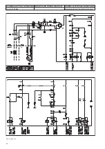
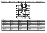
Page 51: ...QUADRO DI COMANDO CONTROL BOX STEUERTAFEL TABLEAU DE COMMANDE PANEL DE MANDO...
Page 57: ......


