background image

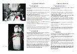
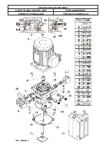
Fig.20 - Abb.20

I

ATTENZIONE

I

WARNING

I

ATTENTION

I

AC H T U N G

I

ATENCION

·

IL CARICO NOMINALE NON PUO’ ESSERE PRESO DA “ZERO”

·

IT IS NOT POSSIBLE TO LIFT THE NOMINAL LOAD FROM" ZERO"
POSITION

·

LA CHARGE NOMINALE NE PEUT PAS ETRE PRISE DE “ZERO”

·

DIE NENNLAST KANN NICHT AB DER NULLSTELLUNG GEHOBEN
WERDEN

·

LA CARGA NOMINAL NO PUEDE SER TOMADA DE “ZERO”

Fig.21 - Abb.21

CAP. 5

FUNZIONAMENTO

I comandi del sollevatore sono situati sulla centralina di comando, dove
trovano alloggiamento: il gruppo motore-pompa idraulica, i gruppi elet-
trovalvole e gli attacchi per l’ allacciamento alla rete elettrica.
I comandi sulla consolle sono indicati in fig.20:

1- PULSANTE DI SALITA:

Tipo “ uomo presente presente “ funziona sotto tensione a 24V, e se premu-
to, aziona il motore e i meccanismi che attuano la salita del sollevatore.

2- INTERRUTTORE GENERALE:

POSIZIONE “ 0 “: Il sollevatore non è in tensione, ed è possibile lucchettare l’
interruttore per impedire l’ uso del sollevatore in caso di guasto.
POSIZIONE “ 1 “: Il sollevatore è in tensione.

3- SPIA ALIMENTAZIONE:

Segnala che il quadro di comando è sotto tensione.

4- PULSANTE ESCLUSIONE FINECORSA ALTO:
POSIZIONATO ALL'INTERNO DELLA CONSOLLE DI COMANDO

Tipo “ uomo presente “ funziona sotto tensione a 24V, ed esclude il mi-
cro di fine corsa salita.

5- PULSANTE DI DISCESA:

Tipo “ uomo presente “ funziona sotto tensione a 24V, e se premuto,
aziona il motore e i meccanismi che attuano la discesa del sollevatore.

A 45cm dal suolo il sollevatore si arresta, per compiere la discesa com-
pleta rilasciare e ripremere il pulsante "discesa".

SEQUENZA DI FUNZIONAMENTO

Prima di salire/scendere dal sollevatore, assicurarsi che le pedane siano alla
minima altezza.
Salire con l’ autovettura sul sollevatore a “ passo d’ uomo “, posizionando la
stessa come indicato in fig. 21.
Posizionare gli appositi tamponi in gomma sulla pedana del sollevatore in
corrispondenza dei punti di presa consigliati dal costruttore dell’ autovettura.
Le rampe di salita possono avere la funzione di prolunga purchè si abbia la
certezza di averle agganciate correttamente prima di sollevare il carico.
Spegnere il motore e innestare il freno di stazionamento dopo aver posizio-
nato l’ auotovettura sul ponte sollevatore e ricordarsi di disinserire la leva del
cambio posizionandola sul “ folle “.

In fase di salita/discesa, il sollevatore deve essere costantemente osservato
insieme al suo carico.

Premere il pulsante ‘SALITA’ no. 1 in fig. 20 e tenerlo premuto finche il ponte
raggiunge l’altezza desiderata.

Per abbassare Il carico, premere il pulsante ‘DISCESA’ no. 5 (fig.20).

A 45cm dal suolo il sollevatore si arresta, per com-

piere la discesa completa rilasciare e ripremere il pul-

sante "discesa" "5".

CHAPTER 5

OPERATION

Car lift controls are located in the control box, where the motor-hydrau-
lic pump unit, the solenoidvalves and the connections to the elec-
tric-pneumatic and hydraulic system are also located.
Controls on the board are the following in fig.20:

1 - LIFTING PUSH BUTTON:

“Dead man control”, 24V operated, when pressed, the motor and the

lifting mechanism are operated.

2 - MAIN SWITCH:

“O” POSITION: lift is not powered. The switch can be padlocked to pre-
vent the use of the lift in case of failure.
“1" POSITION: lift is powered.

3 - FEEDING PILOT LIGHT:

it indicates that the control board is powered.

4- UPPER LIMIT SWITCH BY-PASS-BUTTON
POSITIONED INSIDE THE CONTROL UNIT

“Dead-man-type” switch, operates under 24 V and cuts off the upper li-
mit microswitch.

5 - LOWERING PUSH BUTTON:

“dead man control”, 24V operated, when pressed, the motor and the lowe-

ring mechanism are operated.

At a height of 45 cm from ground the lift will automatically stop. In order
to carry out the remaining descent stroke, release the descent button
and press it again until the lift has reached its ‘zero’ position.

OPERATION SEQUENCE

Make sure the platforms are at the minimum height before lifting/lowering the
car lift.
Get on the vehicle and crawl on the car lift; be sure the vehicle is properly
positionated (see fig.21).
Place the proper rubber pads on the platform so that they are in line with the
lifting points specified by the manufacturer.
The on-ramps can be used as extensions if these are properly hooked befo-
re lifting the vehicle.
Switch off the motor and engage the parking brake after placing the vehicle
on the car lift; furthermore disengage the shift lever and move it to the “neu-
tral” position.

Carefully check the car lift and its load during lifting/lowering operations.

Press the ‘UP’-button Nr. 1 (fig.20) until the lift has reached the required he-
ight.
In order to bring the lift down to the floor, press the ‘DOWN’-button nr. 5 (fig.
20).

At a height of 45 cm from ground the lift will automa-

tically stop. In order to carry out the remaining de-

scent stroke, release the descent button and press it

again until the lift has reached its ‘zero’ position.

35

Summary of Contents for STRATOS SRM

Page 1: ...I GB F D E PONTE SOLLEVATORE A FORBICE SCISSORS LIFT PONT L VATEUR A CISEAUX ELEKTROHYDRAULISCHE SCHERENHEBEB HNE ELEVADOR DE TIJERAS STRATOS SRM N 15...

Page 2: ......

Page 3: ...B HNE ELEVADORES DE TIJERAS PARA VEH CULOS Modello Model Modell Mod le Modelos STRATOS SRM COSTRUTTORE MANUFACTURER HERSTELLER CONSTRUCTEUR FABRICANTE WERTHER INTERNATIONAL S p A Via F BRUNELLESCHI 12...

Page 4: ...i Pag 39 Appendice A Informazioni particolari Pag 43 Appendice B Parti di ricambio Pag 45 Contents Packing transport and storage Page 4 Introduction Page 6 Chapter 1 Description of the machine Page 10...

Page 5: ...ng Seite 7 Kap 1 Beschreibung Scherenhebeb hne Seite 11 Kap 2 Technische Daten Seite 13 Kap 3 Sicherheit Seite 15 Kap 4 Installation Seite 19 Kap 5 Betrieb und Gebrauch Seite 36 Kap 6 Wartung Seite 38...

Page 6: ...it e eventuali danni che il sollevatore abbia subito durante il trasporto Rispettare infine al momento dello scarico o del carico della merce i propri punti di presa come indicato in figura PACKING TR...

Page 7: ...luss Gummi puffer und Schlauchschutzgeh use IWARNUNG TRANSPORT Abb 2 Das Packgut kann mittels Hubwagen Kr nen oder Br ckenkr nen ge hoben und bewegt werden Beim h ngendem Transport mu immer eine zweit...

Page 8: ...n risponde di alcun danno a persone veicoli od oggetti causati dagli interventi sopracitati se effettuati da persona le non autorizzato o da un uso improprio o non consentito del sol levatore INTRODUC...

Page 9: ...dbuch jederzeit zur Verf gung haben INSBESONDERE WIRD EMPFOHLEN DAS KAPITEL 3 WIEDER HOLT ZU LESEN DENN DIESES KAPITEL ENTH LT WICHTIGE IN FORMATIONEN UND HINWEISE BEZ GLICH DER SICHERHEIT Die Scheren...

Page 10: ...citure operatore e ma nutentore il cui significato il seguente OPERATORE persona addetta all uso del sollevatore MANUTENTORE persona addetta alla manutenzione ordinaria del sol levatore This manual in...

Page 11: ...n korrekt auslegen zu k nnen und ber die allgemeinen und spezifischen Unfallverh tungsma nahmen des jeweiligen Landes in dem die Scherenhebeb h ne aufgestellt wird unterrichtet sein Die gleichen Krite...

Page 12: ...icolare esso non idoneo per operazoni di lavaggio sollevamento di persone ponteggio Chapter 1 Description of the machine Scissor lift is able to lift any kind of car and van whose weight is not hi ghe...

Page 13: ...eis Rohrbruchsicherung Mechanische Sicherheitssperren Vorrichtung zum manuellen Absenken bei Strom Ausfall berstr mventil Absenkgeschwindigkeitskontrollventil Die Scherenhebeb hne besteht aus den folg...

Page 14: ...ado di contaminazione non superiore alla classe 18 15 secondo normativa ISO 4406 come IP HYDRO OIL 32 SHELL TELLUS T 37 o equivalenti CHAPTER 2 SPECIFICATIONS TECHNICAL DATA Operation electro hydrauli...

Page 15: ...g 230 400V 3PH 5 Frequenz 50 Hz Polanzahl 2 Drehzahl 2800 UpM Bauform B14 Isolationsklasse F Strom Verbrauch 230V 14 4A 400V 7 5 A Betriebskat S3 12 Min Schutzklasse IP54 HYDRAULISCHES ANTRIEBSAGGREGA...

Page 16: ...chiosa una illuminazione non idonea Verificare che tutte le zone del sollevatore siano ben illuminate ed in maniera uniforme in conformit a quanto previsto dalla normativa vigente nel luogo di instal...

Page 17: ...nungsper sonal erlaubt unter dem Lift zu stehen 3 Der Bediener hat sicherzustellen da die Gefahrenzone vor dem Hebe oder Absenkvorgang leer ist 4 Benutzen Sie die Maschine niemals ohne die vorgesehene...

Page 18: ...a fig 7 12 Climbing on the platforms when lifting the vehicle or when the same has been already lifted is trictly forbidden 13 Any use of the car lift other than what herein specified can cause seriou...

Page 19: ...CHALTER Stoppt die Senkbewegung der Hebeb hne wenn auf ein Hindernis unter den Fahrschienen aufgefahren wird AUTOM EUROSTOP IN 45 CM H HE AB BODEN Ein Mikroschalter stoppt die Hebeb hne 45 cm ab Boden...

Page 20: ...per compiere la discesa completa rilasciare e ripremere il pulsante discesa CHAPTER 4 INSTALLATION IWARNING SKILLED AND AUTHORIZED PERSONNEL ONLY SHOULD BE ALLOWED TO PERFORM THESE OPE RATIONS FOLLOW...

Page 21: ...die Bedienungsseite und f r Laufbahnen in Notf llen ist ebenfalls weiterer Abstand erforderlich Der entsprechende Raum mu vorher f r die Stromzuf hrung Leitungen eingerichtet sein Die H he die ses Ra...

Page 22: ...trifase occorre cambiare il collegamento sul trasformatore e sul motore vedere morsettiera sul trasformatore e sul motore stesso fig 10 IWARNING Unpack the goods and check for possible damage before i...

Page 23: ...wie folgt aus abb 9 ffnen Sie die obere Konsole ffnen Sie die vordere T r Mit der richtigen Anschlusskasten schlie en Sie das Elektro der al lgemeinen Schalterkabel Achten Sie darauf dass das Kabel du...

Page 24: ...SCHEMA ELETTRICO TRIFASE THREE PHASE WIRING DIAGRAM SCH MA LECTRIQUE TRIPHAS SCHALTPLAN ESQUEMA ELECTRICO TRIFASICO Fig 11 Abb 11 22...

Page 25: ...to PT1 PT2 KM1 B4085 Teleruttore comando motore Motor contactor Contacteur moteur Motor Start Relais Teleinterruptor control motor SQAR1 SQAR2 B7263 Micro antiribaltamento Tip over prevention microswi...

Page 26: ...SCHEMA ELETTRICO MONOFASE MONO PHASE WIRING DIAGRAM SCH MA LECTRIQUE MONOPHAS SCHALTPLAN ESQUEMA ELECTRICO MONOFASICO Fig 11b Abb 11b 24...

Page 27: ...o PT1 PT2 KM1 B4085 Teleruttore comando motore Motor contactor Contacteur moteur Motor Start Relais Teleinterruptor control motor SQAR1 SQAR2 B7263 Micro antiribaltamento Tip over prevention microswit...

Page 28: ...SCHEMA COLLEGAMENTO ELETTRICO ELECTRIC WIRING DIAGRAM CONNECTION TO ELECTRIC CARD SCH MA DES RACCORDEMENTS LECTRIQUES ELEKTRISCHER SCHALTPLAN ESQUEMA CONEXION ELECTRICA Fig 12 Abb 12 26...

Page 29: ...RA ELEKTRISCHER SCHALTPLAN 1 2 Kippschutz 3 Oberer Begrenzungsschalter 4 Fussschutz Mikroschlater Bemerkung Stellen Sie folgende Verbindungen Her stellen VERBINDEN SIE ALLE KABEL DIE AUS DEM MASCHINEN...

Page 30: ...surpression berdruckventil V lvula de m xima 8 Pompa Pump Pompe Pumpe Bomba 9 Motore Motor Moteur triphas Elektromotor Motor trif sico 10 Elettrovalvola doppia tenuta circuito PT1 PT2 Double sealed s...

Page 31: ...HER SCHALTPLAN SCHLAUCHANSCHL SSE RE HYDRAULIKEINHEIT ESQUEMA CONEXION HIDR CENTRAL DE MANDOS DER A D1104 Mandata P1 PT1 PT2 Delivery P1 PT1 PT2 Alimentation P1 PT1 PT2 Zulauf P1 PT1 PT2 Tubo de envio...

Page 32: ...ER SCHALTPLAN SCHLAUCHANSCHL SSE LI HYDRAULIKEINHEIT ESQUEMA CONEXION HIDR CENTRAL DE MANDOS IZQ A D1104 Mandata P1 PT1 PT2 Delivery P1 PT1 PT2 Alimentation P1 PT1 PT2 Zulauf P1 PT1 PT2 Tubo de envio...

Page 33: ...discesa fino alla chiusura completa delle pedane Ripetere l operazione descritta al punto 6 men silmente con il sollevatore a vuoto per mantene re carico il cicuito oleodinamico HYDRAULIC CONNECTION...

Page 34: ...mittel die H he von 1400 mm erreichen 4 Die Leitungen C und D unter Beachtung des Schemas auf Abb 14 15 anschlie en 5 F llen Sie weitere 6 Liter l in den Tank 6 AUF Knopf 1 und gleichzeitig den berbr...

Page 35: ...prima della fase di travaso micro antiribaltamento interponendo un ostacolo sotto alle piattaforme il sollevatore deve arrestarsi micro salvapiedi il sollevatore deve arrestarsi a 45cm dal pavimento...

Page 36: ...ein Loch Reinigen Sie die L cher und setzen Sie die richtigen Eins tze FISCHER FH 15 25 o HILTI HST M12 x145 oder hnliches mit leichten Ham merschl gen ein Vergewissern Sie sich vor dem Anziehen der S...

Page 37: ...e essere costantemente osservato insieme al suo carico Premere il pulsante SALITA no 1 in fig 20 e tenerlo premuto finche il ponte raggiunge l altezza desiderata Per abbassare Il carico premere il pul...

Page 38: ...loslassen und erneut dr cken bis die B hne die Nullstellung erreicht hat ARBEITSABLAUF Vor dem Heben der Scherenhebeb hne m ssen sich die Aufnahmeplattfor men in der untersten Position befinden Gehen...

Page 39: ...AUSTO L olio esausto che viene estratto dalla centralina e dall impianto durante il cambio olio dev essere trattato come prodotto inquinante pertanto dovr essere smaltito secondo le prescrizioni della...

Page 40: ...UNTERLASSEN WERDEN DIESE EMPFEHLUNG ZU RESPEKTIEREN WIRD DER HERSTELLER VON ALLER VERANT WORTUNG DIE IN DER GARANTIE FESTGELEGT IST BEFREIT 1 Die Scherenhebeb hne mu mindestens ein Mal pro Monat gere...

Page 41: ...tenza Sostituire gruppo pompa Non si riesce a solle vare la portata nomi nale Staratura della val vola di pressione massima fig 13 Pompa danneggiata Richiedere intervento tecnico per registrare o sost...

Page 42: ...en Dr cken Sie den Herauf fahr Schalter und entfernen Sie das Hindernis Absenkbewegung zu langsam Absenkkontrollventil berpr fen Kundendienst verst ndigen Hydraulikpumpe ar beitet Hebe b hne kann nich...

Page 43: ...ore inizier la discesa A discesa ultimata riavvitare i po melli A B Chiamare servizio assistenza Chiamare servizio assistenza TABLE 2 TROUBLES POSSIBLE REASON SOLUTION The lift doesn t go down Lack of...

Page 44: ...der Elektrik Senkventil ffnet nicht Fehler in der Elektrik Handhabung Schrauben Sie den manuellen Herun terfahr Schalter ab A B Knopf Abb 22 Die Hebeb hne startet den Vorgang Herunterfahren Sobald vo...

Page 45: ...gli operatori de vono adottare tutte le precauzioni dettate dalle norme per la prevenzio ne infortuni contro la persona casco guanti scarpe etc vigenti nel paese di installazione della macchina e risp...

Page 46: ...ltigen Gesetzen des entsprechenden Lan des der Installation FEUERSCHUTZ Diese Maschine ist nicht feuergef hrlich jedoch mu der Raum in dem die Hebeb hne betrieben wird den Richtlinien f r Feuerverh t...

Page 47: ...cnico specializzato autorizzato dal costruttore secon do quanto previsto nell allegato modulo Certificato di Manutenzione che deve essere compilato ad ogni controllo Tali documentazioni devono essere...

Page 48: ...t f r Batterien l f r Bremsen oder anderen stark tzenden Fl ssigkeiten in Ber hrung kommen Nach der Verwendung der Hebeb hne ist diese insbesondere in den Wintermonaten von Wasser zu befreien Vorhande...

Page 49: ......

Page 50: ...ESPLOSO SOLLEVATORE EXPLODED VIEW OF THE LIFT EXPLOSIONSZEICHNUNG HEBEB NNE VUE CLAT E L VATEUR DESPIECE ELEVADOR...

Page 51: ...QUADRO DI COMANDO CONTROL BOX STEUERTAFEL TABLEAU DE COMMANDE PANEL DE MANDO...

Page 52: ...CENTRALINA OLEODINAMICA OLEODYNAMIC CONTROL UNIT HYDRAULIKEINHEIT CENTRALE HYDRAULIQUE CENTRALITA HIDRAULICA...

Page 53: ...DE REGULACI N DE PRESI N DE FUNCIONAMIENTO 1 4 LT3 B1721 VALVOLA MAX VMP18 100 350 BAR MAX PRESSURE VALVE VMP18 100 350 BAR UEBERDRUCKVENTIL VMP18 100 350 BAR CLAPET DE PRESSION MAX VMP18 100 350 BAR...

Page 54: ...PIN BOLZEN AXE PERNO B4530 RULLO RAMPA STRATOS SR ZB BALANCE RAMP ROLLER FFUEHRUNGSBUCHSE ROULEAU RAMPE BASCULANTE RODILLO RAMPA BASCULANTE B4536XX KIT RAMPA BASCULA DX S SR VER KIT BALANCE RAMP DX A...

Page 55: ...E CARTE ELECTRIQUE PLACA ELECTRONICA B7256 MICROINTER SIC CAB M12 FF4515 MICROSWITCH MIKROSCHALTER CONTACT MICROINTERRUPTOR B7263 MICROIN SIC CAB M12 90 FF4515 MICROSWITCH MIKROSCHALTER CONTACT MICROI...

Page 56: ...0X100 PF UNI 5737 ZB SECHSKANTSCHRAUBE M10X100 PF UNI 5737 ZB VIS TH M10X100 PF UNI 5737 ZB TORNILLO M10X100 PF UNI 5737 ZB R1236 GIUNTO TRASC POMPA CEN 262 CONNECTING PUMP GELENK PUMPE ACCOUPLEMENT D...

Page 57: ......

Page 58: ...tuel fuites sur le circuit hydraulique Kontrolle auf eventuelle Leckagen des Hydraulikkreislaufs 2h Stato generale dell azionamento General drive condition tat g n ral de l actionnement Allgemeiner Zu...

Page 59: ...rkl rer hermed at autol fter model hereby we declare that the lift model Vi f rklarer h rmed att billyft model hiermit erkl ren wir da die Hebeb hne Type verklaren hiermee dat STRATOS SRM Matricola N...

Reviews: