Start-up
CTW900 | 59
5.
Set the speed reference for the maximum value (P0001 = P0134).
6.
Monitor with the oscilloscope the “IA” test point on the IC900 electronic interface board. Use as
reference one of the GND points of this board (“GND8”, for example).
7.
Close the switch connected to the Digital Input 2 (DI2), which must be set to the ‘Run/Stop’ function.
8.
Close the switch connected to the digital input configured as General Enable for a
period shorter than
three seconds.
9.
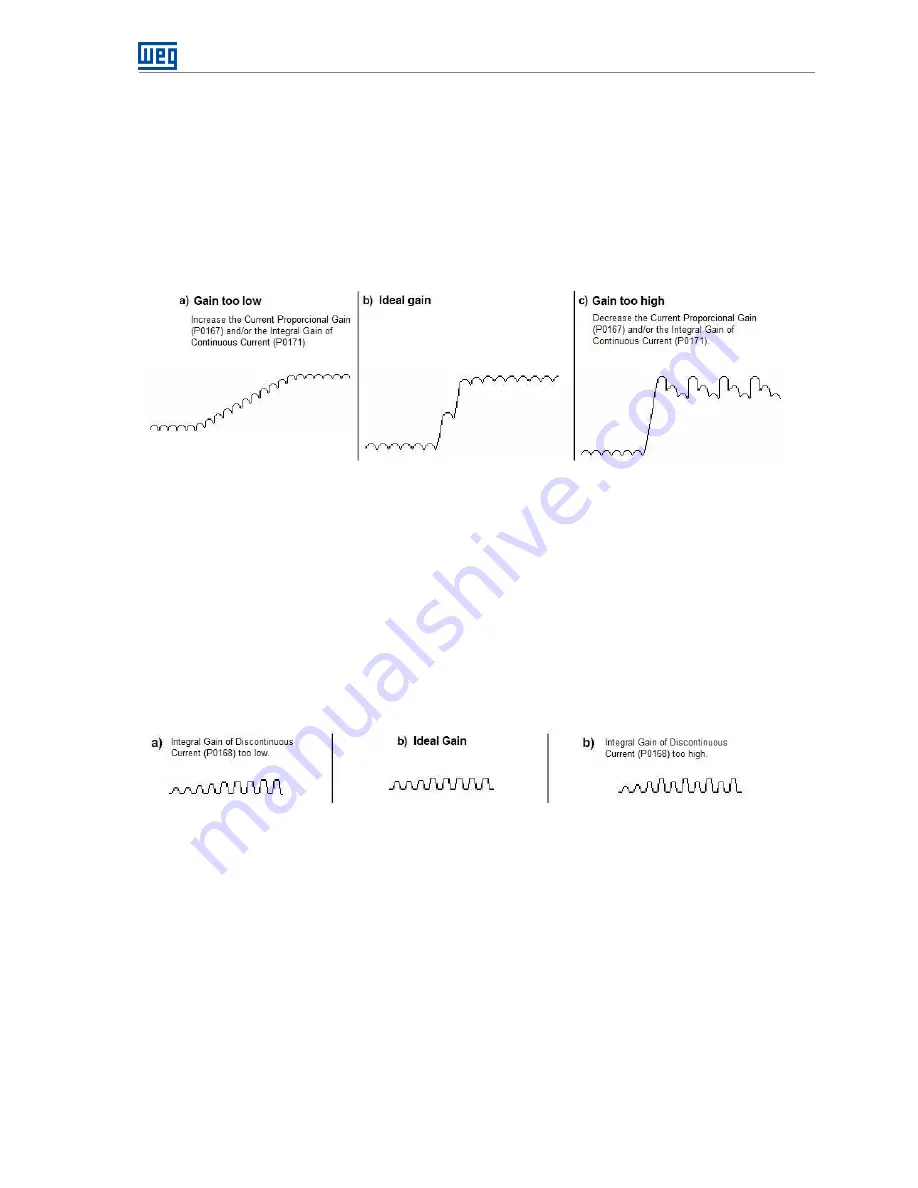
Check the measured signal:
Figure 6.4
– Possible outputs to measure the “IA” signal in the setting of the current regulator
10.
Set P0167 and P0171 until obtaining a wave form similar to that shown in Figure 6.4
b)
. Path to access
P0167 and P0171: Menu
01 PARAMETER GROUPS
26 REGULATORS
101 Current Reg.
11.
Set the speed reference for the minimum value (P0001 = P0133).
12.
Close the switch connected to the digital input configured as General Enable and set the speed
reference so as to obtain an intermittent current on the oscilloscope.
13.
Open the switch connected to the digital input configured as General Enable, wait for a few seconds
and close it again.
14.
Check the measured signal:
Figure 6.5
– Wave form for the “IA” signal with intermittent current
15.
Set P0168 until obtaining a wave form similar to that shown in Figure 6.5
b)
. Path to access P0168:
Menu
01 PARAMETER GROUPS
26 REGULATORS
101 Current Reg.
16.
Remove the ‘Run’ command (open the DI2 switch) and disable the converter (open the ‘General
Enable’ switch).
17.
Enable the Field Control again (P0297 = Enabled) and the Stall protection (P0355 > 0 %). Also set the
Positive Torque Current Limit (P0169) according to the application (factory setting: P0355 = 5 % and
P0169 = 25 %).
6.4.3
Optimization of the Speed Regulator
1.
Set the speed reference for 75 % of the motor maximum speed.


