Part Number: 4604223 — Rev:0
13
Section 1
Section 1
Baumer Sensor Faults
1. To check the baumer sensor the easiest method is as
below
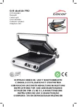
a. Enter the gap calibration menu.
b. Select the +/- button.
2. 2.
This will now show you the actual read out of the
rear and front sensor.
a. The reading is a live reading so if you place a metallic
object such as a Gapping tool between the sensor and
target the value in the box should become smaller
b. The number is a reading of the physical gap between
the bottom of the sensor and the target below.
c. If nothing happens you can then remove the platen
arm lid. In the lid you will see the top of the sensor
will have a red light. If you place your metallic object
between the sensor and target you should see the red
light becomes dimmer as the distance shrinks.
d. If this happens but the reading on the UI does not
change you can remove the black wire from the sensor
and swap the wire with the black wire from the other
sensor. This will now change the sensor position.
e. Example. If you had a failed rear sensor and swapped
the black wire this would now become the front sensor.
f. If the reading on the UI now changes when you change
the distance of the sensor and target this proves the
sensor is ok.
g. You can now try the other sensor and if that does not
change then the issues is with the wiring harness (there
is a connection by the actuator so check this is correctly
connected before assuming a new harness is required.
h. If after the test the sensor still did not change the
reading, then it is the sensor that is at fault and needs
replacing.
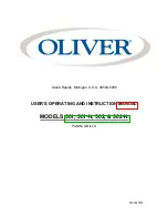
Replacing a Baumer sensor
1. Look at the top of the sensor and note how many threads
are visible.
a. Remove the 3 wires (noting their position)
b. Loosen the locking nut and unscrew the sensor
(counter clockwise to bring the sensor out the top of
the arm)
c. Insert the new sensor and turn it clockwise until you have
the same number of threads visible as the one you
removed.
d. Rewire the sensor
e. Turn on the grill and go to the gap calibration screen
then the +/- screen so you can see the read out from
the switch.
f. Referencing the Baumer-thread relationship set the
sensor to the correct reading based on the guide given.
(Be careful not to over stress the wires are you turn the
sensor) Once the reading is in the correct range tighten
the locking nut.
g. Pop the wires out of the terminals again to remove any
twists and stress on the cable then reinsert them.
h. Refit the lid and the job is complete.
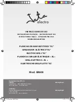
REAR Shoulder Bolt
Allowed Adjuster
Nut Setting (MIL)
Allowed Rear Sensor Value
MIN
MAX
40
190
220
70
220
250
100
230
270
FRONT Shoulder Bolt Adjustment
Average Threads
Showing
Allowed Front Sensor Value
MIN
MAX
BOTH NOTCHES MUST BE VISIBLE
NOTCH ONLY
198
238
1/2 THREAD
214
254
1 THREAD
230
270
1-1/2 THREADS
246
286
2 THREADS
262
302
2-1/2 THREADS
278
318
A MAXIMUM OF THREE THREADS CAN BE SHOWING