A
QUA
L
OGIC
COMPANION
WATER
HEATER
—
Product Manual
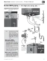
Boiler/CWH piping —
155 / Right-side mixing valve
CONNECTIONS TO BOILER
AND SYSTEM
4HE!QUA,OGIC#7( CANBEPLACEDWITHITS
$(7CONNECTIONSONTHELEFTSIDEORONTHE
RIGHTSIDEBYROTATINGTHEUNITDEGREES
4HIS INSTRUCTION IS FOR INSTALLATIONS WITH THE
#(7WITHITS$(7CONNECTIONSONTHE2)'(4
SIDE4HE BOILER SHOWN MUST BE A MODEL
7-
"OILERWATER2%452.CONNECTIONFROM!QUA
,OGIC#7(
"OILERWATER3500,9CONNECTIONTO!QUA,OGIC
#7(
7ATERHEATER40RELIEFVALVECONNECTION
T&P relief valve is shipped loose with the Aqua Logic (CWH)
for field installation.
5PPERTANKTEMPERATURESENSOR
$(7SUPPLYANDRETURNCONNECTIONSONSIDE
Follow instructions on page 7 to install the mixing valve that
is supplied with the Aqua Logic (CWH).
"OILERHOTWATER3500,9TO!QUA,OGIC#7(
"OILERWATER2%452.FROM!QUA,OGIC#7(
'ASSUPPLYCONNECTIONTOBOILER
Installer must provide hard piping or flexible gas line between
boiler connection and gas line connection (item 20).
#ONDENSATETRAPCONNECTIONTOBOILER
!QUA,OGIC#7( BOILERWATERCIRCULATOR
SHIPPEDLOOSEWITH!QUA,OGIC#7(
This circulator is shipped loose with the Aqua Logic (CWH).
The circulator flows boiler water through the internal heat
exchanger coil. The WM97+ boiler control cycles the circula-
tor based on domestic water demand.
The circulator must be installed in the location and flow di-
rection shown on the next page. Otherwise, the water heater
will not perform correctly.
The circulator is 3-speed with an integral flow/check valve.
The circulator speed MUST be set at “1(LO)” when
connected to a WM97+70 or 110. The circulator
speed MUST be set at “3(HI)” when connected to
a WM97+155.
#IRCULATORMOUNTINGHARDWARE
SHIPPEDLOOSEWITH
!QUA,OGIC#7(
The lower mounting flange, bolts, nuts and gaskets are
shipped loose for installation with the circulator. Note that
the lower flange must be rotated 10 degrees clockwise rela-
tive to the front face of the Aqua Logic (CWH). Note that the
lower flange must be rotated 10 degrees clockwise relative to
the front face of the Aqua Logic (CWH).
5PPERCIRCULATORmANGEBOILERWATERCONNECTION
SHIPPEDLOOSEWITH!QUA,OGIC#7(
This fitting is shipped loose for field installation in the loca-
tion and position shown on the opposite page.
&LEXIBLEBOILERWATER2%452.LINE
EITHEROFTWO
mEXIBLELINESSHIPPEDLOOSEWITHTHE!QUA,OGIC#7(
Two 1-inch flexible stainless steel hoses are shipped loose for
field installation. Use one hose each for boiler water Aqua
Logic (CWH) supply and return connections. Make sure a
gasket is placed in each the hex fittings on the hose ends. No
pipe dope or tape is needed. DO NOT over-tighten — gasket
would be damaged.
3ERVICETEEv
SHIPPEDLOOSEWITH!QUA,OGIC#7(
Install the service tee in the location shown in this manual
to provide location for the boiler drain valve (item 16). A
bushing, 1”x¾” NPT, is supplied for mounting the boiler
drain valve as shown in this manual.
"USHINGFORMOUNTINGHOSEBIBBDRAINVALVE
SHIPPEDLOOSEWITH!QUA,OGIC#7(
Install the 1” x ¾” bushing in the service tee.
"OILERDRAINVALVEÐv
SHIPPEDLOOSEWITHBOILER
This valve is shipped loose with the WM97+ boiler. It must
be located as shown on the opposite page when the boiler is
connected to a Aqua Logic (CWH).
&LEXIBLEBOILERWATER3500,9LINE
EITHEROFTWO
mEXIBLELINESSHIPPEDLOOSEWITHTHE!QUA,OGIC#7(
Two 1-inch flexible stainless steel hoses are shipped loose for
field installation. Use one hose each for boiler water Aqua
Logic (CWH) supply and return connections. Make sure a
gasket is placed in each the hex fittings on the hose ends. No
pipe dope or tape is needed. DO NOT over-tighten — gasket
would be damaged.
40RELIEFVALVE
SHIPPEDLOOSEWITH!QUA,OGIC#7(
T & P relief valve is shipped loose with the Aqua Logic (CWH)
for field installation in the location shown on the next page.
2ELIEFVALVEDISCHARGEPIPING
The relief valve outlet MUST be piped to a safe discharge
location, following all local codes. See page 9 for instructions
and requirements.
'ASCONNECTIONWITHMANUALGASVALVEUNION
ANDDRIPLEG
GASVALVEISSHIPPEDLOOSEWITHBOILER
The manual gas valve shown on the opposite page is shipped
loose for field installation. Follow all instructions in the
WM97+ Boiler manual for sizing and installing gas connec-
tions. The manual gas valve and piping shown as item 20 must
be installed OUTSIDE the piping access panel and braced/
supported from the wall or other structure. Orient the piping
for best routing through one of the piping access panel sides.
4OBUILDINGGASSUPPLY
#ONDENSATETRAPASSEMBLY
SHIPPEDLOOSEWITHBOILER
The trap assembly is shipped loose for field assembly and
installation. Follow WM97+boiler manual instructions for
trap assembly and installation. Orient the trap for best routing
of the condensate drain line through the right or left opening
in the piping access cover.
#ONNECTTOCONDENSATEDRAINPIPING
Follow all WM97+ Boiler manual instructions for connecting
condensate drain piping.
Part number 635-500-156/1113
16


