


A
QUA
L
OGIC
COMPANION
WATER
HEATER
—
Product Manual
Recirculation
(if used)
(continued)
3. Size the circulator and piping based on the tempera-
ture drop allowed between the water available at the
water heater and the water delivered at the fixture.
a. The return piping will almost always be smaller
than the supply piping, but should never be
smaller than ½” to prevent problems with the
circulator.
4. Make provision for removal of air in all return lines.
Where the returns cannot be vented by topmost
fixtures in the system, install automatic air venting
at the top of the return piping.
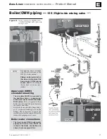
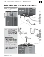
Connecting to the water heater
1. Install the domestic water components as shown
in Figure 6, page 8.
2. See the following pages for piping between boiler
and water heater, boiler lower pipe routing and
Aqua Logic (CWH) relief valve.
a. WM97+70 or 110 boiler:
Mixing valve on right side of CWH: page 12
Mixing valve on left side of CWH: page 14
b. WM97+155
boiler:
Mixing valve on right side of CWH: page 16
Mixing valve on left side of CWH: page 18
Components
(see Figure 9)
2ECIRCULATIONPUMP
1. Little flow is required to maintain a temperature
in the piping.
2. Size of pump depends on minimum flow require-
ments of the mixing valve.
3. Minimum flow rates of the mixing valve must be
maintained (minimum for Honeywell AMX302TLF
is 0.25 GPM).
2ECIRCULATIONPUMPAQUASTAT
1. Used to control the on-off position of the circula-
tor. Aquastat is set 5° to 10° lower than mixed water
outlet of the mixing valve.
2. The pump cannot run continuously — bypass
through the mixing valve will eventually allow the
temperature on the piping to climb to the water
heater temperature during draw periods.
#HECKVALVE
1. Assures the flow of water in one direction.
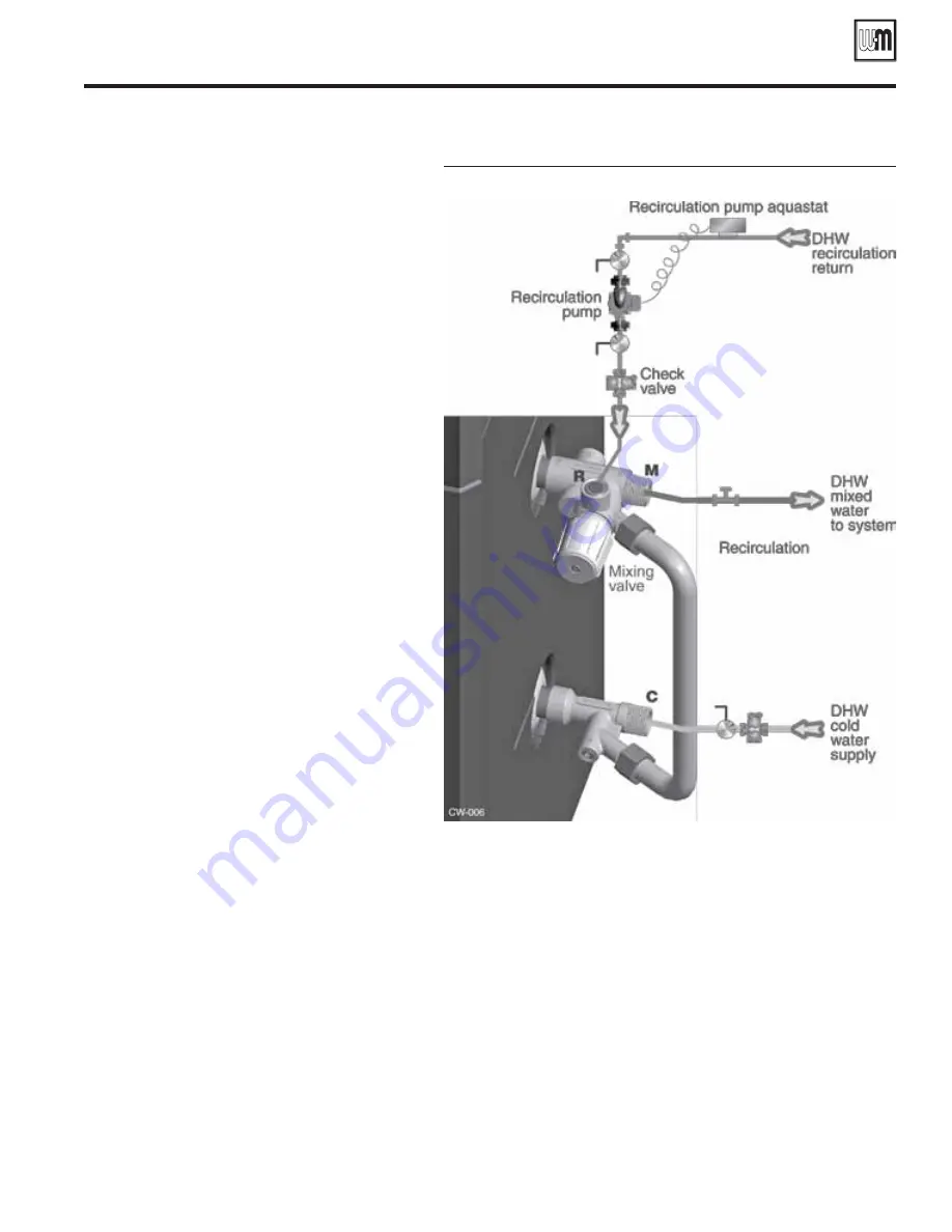
Operation
1. When temperature at recirculation pump aquastat
falls 10° below temperature to be maintained —
recirculation pump turns on.
2. When aquastat reaches temperature — Circulator
turns off.
&IGURE
Recirculation piping at mixing valve
Part number 635-500-156/1113
11