


Brine fog maker, Type Solfog V2
Index: 01
Change date: 12/12/2017
Operating instructions no.: BA DW 018-01 Solfog V2 EN.docx
Page 14 of 39
4.3
Mechanical installation
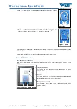
Assemble the fog making
The Solfog V2, except for the roll carrier and the brine solution, is supplied ready for use. It must
be installed at a place that is easy to access.
Fix the assembly plate with 4 screws tightly on the wall and secure a good accessibility.
Assemble the button plate (option)
The button plate is fixed with 4 screws on the wall.
ATTENTION !
Avoid penetration of humidity behind the button plate!
4.4
Hydraulic installation
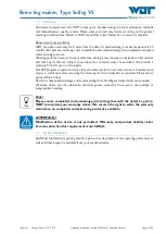
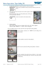
Tube the
outlet pipe (16), see Figure 1
, until the fog inlet orifice in the cabin. The material is not
included in the scope of delivery!
Assemble piping
Search an appropriate place for the fog inlet in the cabin.
Drill a 40 mm big opening in the cabin wall.
Tube the fog conduct from the brine fog maker to the cabin with d 40mm.
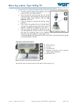
The fog maker pipe
must be installed with a slope of 1cm for each 1m line length (=1%) to the fog maker device!
The conduct must have a maximum length of 4m. In the conduct maximum 5 bows (no angles)
may be installed.
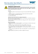
Fix the rosette onto the sauna wall
Picture 7, assembly fog maker pipe
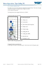
CAUTION !
Install the fog conduct upwards and without water pocket, so that the condensate can
return and does not stay in the conduct. This is necessary for hygiene, so that no germs
or bacteria can be formed! When the conduct cannot be installed upwards or with a
water pocket, a drainage possibility must be foreseen.
Inner cone
Panel
Cabin exterior
Cabin interior
Fog inlet from the fog
maker device


