20
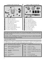
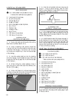
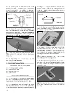
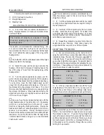
Photo # 31
☛
Scribe the plastic several times until the knife cuts
completely through. Don't try to cut completely through
the plastic all at once.
❑
3) Reinstall the cowling using the four wood screws
you removed previously. Reverse the removal steps for
installation.
CUTTING THE AIR-EXIT HOLE
❑
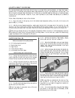
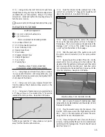
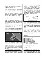
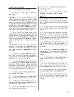
4) Using a ruler and a pen, measure back 1" from
the back edge of the wing saddle and draw a mark in the
center of the fuselage.
❑
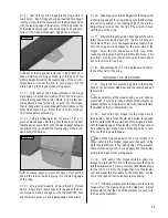
5) Using a modeling knife, carefully cut a 3/4"
diameter hole through the bottom of the fuselage at the
mark you drew.
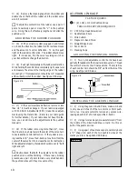
See photo # 32 below.
intake holes must be cut into the cowling and air-exit holes
must be cut into the bottom of the fuselage.
❑
1) Using a # 0 phillips screwdriver, remove the four
wood screws that hold the cowling in place. Remove the
cowling and set the screws aside.
❑
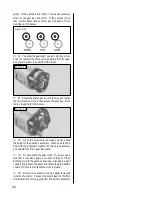
2) Using a modeling knife, very carefully cut out
the two air-intake holes in the front of the cowling.
See
photo # 31 below.
Photo # 32
INSTALLING THE PROPELLER
AND SPINNER ASSEMBLY
❑
6) Using a modeling knife, remove the nylon spin-
ner backplate adapter (that fits firmly over the propeller
shaft) from the plastic spur and press it firmly into the
spinner backplate.
❑
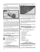
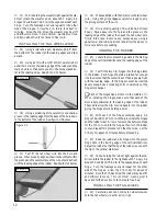
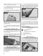
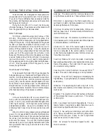
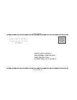
7) Slide the spinner backplate and the propeller onto
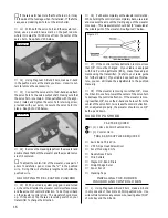
the propeller shaft. Thread the machine screw and washer
into the front of the adaptor and tighten them against the
propeller. Tighten the screw until it is snug. It is not
necessary to overtighten it.
See photo # 33 below.
Photo # 33
☛
Make sure that when you install the propeller it is
centered between the two molded pins; otherwise, the spin-
ner cone will not line up properly with the backplate.
❑
8) Slide the plastic spinner cone over the propeller
and secure it into the molded grooves in the backplate.
Hold the spinner cone in place using two 3mm x 10mm
wood screws. Tighten the screws firmly using a # 0 phillips
screwdriver.
TOOLS AND SUPPLIES REQUIRED
FINAL ASSEMBLY
❑
Kwik Bond Thick C/A
❑
# 0 Phillips Head Screwdriver
❑
Scissors
PARTS REQUIRED
❑
{3} 30mm Velcro
®
Strips
❑
{1} Decal Set
18
❑
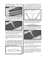
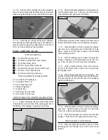
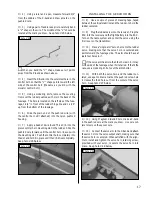
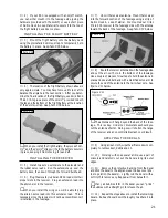
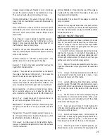
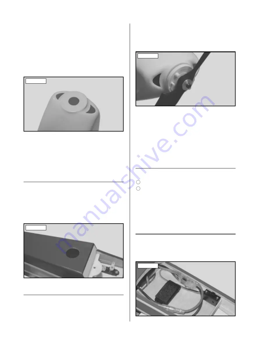
1) Connect the red and black leads from the motor
to the red and black motor leads on the ESC. Mount the
ESC on top of the flight battery deck using a short strip of
Dubro Hook & Loop Material.
See photo # 34 below.
Photo # 34
INSTALLING THE
ELECTRONIC SPEED CONTROL
25

