17
❑
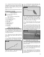
2) Using a ruler and a pen, measure forward 3/4"
from the middle of the Z-bend and draw a mark on the
pushrod wire.
❑
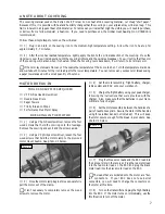
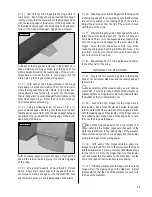
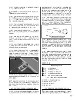
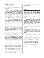
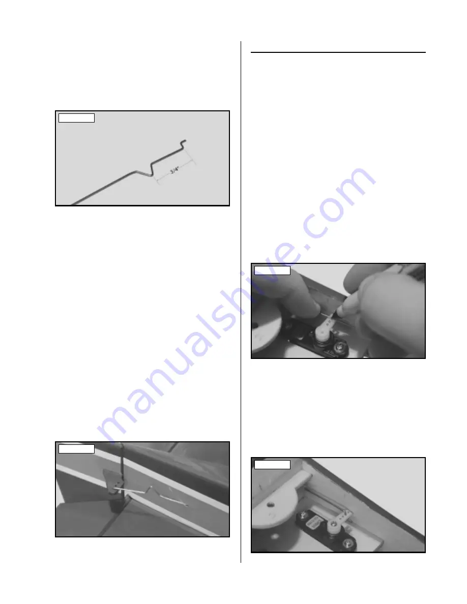
3) Using a pair of needle nose pliers, carefully bend
a "V" shape in the wire. The
middle
of the "V" should be
located at the mark you drew.
See photo # 25 below.
Photo # 25
☛
When you bend the "V" shape, make sure it points
away from the Z-bend as shown above.
❑
4) Insert the Z-Bend into the outermost hole in the
control horn so that the "V" shape points toward the left
side of the control horn (the same as you did with the
elevator control horn).
❑
5) Using a modeling knife, remove the covering
from over the rudder pushrod exit hole in the back of the
fuselage. The hole is located on the left side of the fuse-
lage, 1-3/4" in front of the rudder hinge line and 1-1/16"
up from the bottom of the fuselage.
❑
6) Slide the plain end of the pushrod wire (with
the control horn still attached) into the nylon pushrod
housing.
❑
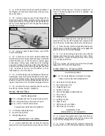
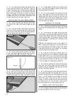
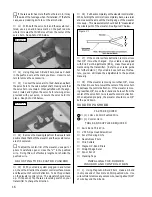
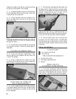
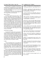
7) Apply a bead of Kwik Bond Thick C/A into the
precut control horn mounting slot in the rudder. Slide the
pushrod wire forward until the control horn lines up with
the mounting slot. Push the control horn completely into
the slot and hold it in place until the C/A dries completely.
See photo # 26 below.
Photo # 26
INSTALLING THE SERVO HORN
❑
8) Use a couple of pieces of masking tape, taped
between the vertical stabilizer and the rudder, to hold the
rudder centered.
❑
9) Plug the rudder servo into the receiver. Plug the
ESC into the receiver and the flight battery into the ESC .
Turn on the radio system and center the servo using the
trim lever on the transmitter.
❑
10) Place a "single arm" servo horn onto the rudder
servo, making sure that the servo horn is centered and
points toward the fuselage side. The arm should have at
least four holes in it.
☛
If the servo arm has more than four holes in it, it may
hit the side of the fuselage when it's installed. If that's the
case, use a modeling knife to cut the arm shorter.
❑
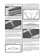
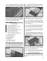
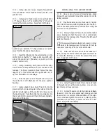
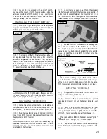
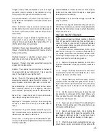
11) With both the servo horn and the rudder cen-
tered, use a pen to draw a mark on the pushrod wire where
it crosses the third hole out from the center of the servo
horn.
See photo # 27 below.
Photo # 27
❑
12) Using Magnum Z-Bend Pliers, make a Z-bend
in the pushrod wire at the mark you drew. Use wire cut-
ters to remove the excess wire.
❑
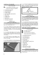
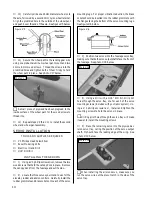
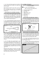
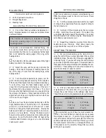
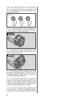
13) Connect the servo arm to the Z-bend and attach
the servo horn to the servo output shaft, making sure that
the servo horn is centered. When satisfied with the align-
ment, install and tighten the servo horn retaining screw,
provided with your servo, to secure the servo horn into
place.
See photo # 28 below.
Photo # 28

