5
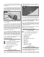
❑
{2} 1mm x 420mm Pushrod Wires
❑
{2} 1mm x 110mm Pushrod Wires
❑
{2} Control Horns
TOOLS AND SUPPLIES REQUIRED
❑
Kwik Bond 5 Minute Epoxy # 887560
❑
Kwik Bond Thin C/A # 887500
❑
Kwik Bond Thick C/A # 887510
❑
# 0 Phillips Head Screwdriver
❑
# 1 Phillips Head Screwdriver
❑
Excel Modeling Knife # 692801
❑
Needle Nose Pliers
❑
Wire Cutters
❑
Magnum Z-Bend Pliers # 237473
❑
Electric or Hand Drill
❑
1/16" Drill Bit
❑
5/64" Drill Bit
❑
Straight Edge Ruler
❑
Builder's Triangle
❑
220 Grit Sandpaper w/Sanding Block
❑
Pen or Pencil
❑
Waxed Paper
❑
Scissors
❑
Masking Tape
❑
Rubbing Alcohol
❑
Paper Towels
❑
NHP Epoxy Mixing Sticks # 864204
❑
NHP Epoxy Mixing Cups # 864205
❑
Trinity Break-In Drops # 840365
❑
Performance Plus Motor Spray # 340186
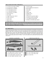
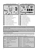
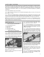
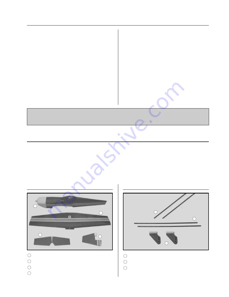
We have organized the parts as they come out of the box for easier identification during assembly. Each photo below
represents the parts that are required in a main section of the assembly process. Before you begin assembly, group the
parts like we show. This will ensure that you have all of the parts before you begin assembly and it will also help you
become familiar with each part. The corresponding part number is listed first, then the quantity of that particular part,
along with a short description of the part. As you proceed through assembly, you will notice the same part number
listed next to a particular part necessary for that step. If you have any questions as to what that part might be, refer back
to this section.
KIT CONTENTS
AIRFRAME ASSEMBLIES
PUSHROD ASSEMBLIES
1
2
3
4
5
6
7
❑
{1} Fuselage w/Motor, Cowling & Canopy Deck
❑
{1} Prejoined Wing w/Ailerons & Hinges
❑
{1} Horizontal Stabilizer w/Elevator & Hinges
❑
{1} Vertical Stabilizer w/Rudder & Hinges
Because Z-Bends are used to connect the pushrods at both the servo ends and the control surface ends, we highly
suggest purchasing a Z-Bend tool to make these bends. You can make Z-Bends using needle nose pliers; however, it
is difficult, especially in the tight spaces of the fuselage.
1
2
3
4
5
6
7


