background image

CLS200 Series User’s Guide

Chapter 8: Troubleshooting and Reconfiguring

152

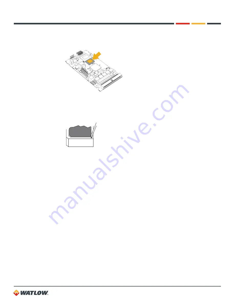
8.  Locate the EPROM on the processor board. The EPROM is a 32-pin socketed chip that is 

labeled with the model, version and checksum.

Figure 8.5


— EPROM  Location

9.  Remove the existing EPROM from its socket with an IC extraction tool or a jeweler’s flathead 

screwdriver.

Figure 8.6


— Remove  EPROM

10. Carefully insert the new EPROM into the socket. Make sure that the chip is oriented so that its 

notch fits in the corresponding corner of the socket.

11. Reverse steps 3 through 7 to reassemble the unit. However, at step 6 insert the two-board 

assembly straight in to the carrier making sure all four arms latch on the boards.

12. Power up the controller.

13. Re-enter the controller settings, if necessary.

Removing or Replacing the Battery

The lithium battery in the battery-backed RAM module on the processor board should be removed 
and disposed of properly if decommissioning the controller. It may also be replaced, if needed during 
the life of the controller.

To remove the battery:

1.  Follow steps 1 to 7 of the procedure 

Replacing the EPROM on page 150

 to access the 

processor board.

2.  Locate the battery backed RAM module. See 

Figure 8.10 — Single-Ended Input Circuit in 

Sixteen-Loop Controllers on page 157

.

3.  Insert a small flat blade screwdriver vertically into the slot on one side of the RMA module.

4.  Angle the screwdriver handle toward the center of the RAM chip gently until the side with the 

Summary of Contents for CLS200

Page 1: ...CLS200 User s Guide...

Page 2: ...only Avertissements Attentions et Remarques AVERTISSEMENT Le r gulateur peut s av rer d faillant avec un r gime de puissance de sortie 0 ou 100 Pour viter tout risque de d c s blessure personnelle en...

Page 3: ...name Phone number Method of return shipment Your P O number Detailed description of the problem Any special instructions Name and phone number of person returning the product 2 Prior approval and an...

Page 4: ...ctions 35 Wiring Control and Digital I O 36 Output Wiring Recommendations 36 Cable Tie Wraps 37 Digital Outputs 37 Digital Inputs 40 TB18 Connections 41 TB50 Connections 42 Analog Outputs 44 Wiring th...

Page 5: ...arm Setpoint 92 Low Process Alarm Type 92 Low Process Alarm Output Number 92 Alarm Deadband 92 Alarm Delay 93 Manual I O Test 93 Digital Inputs 94 Test Digital Output 94 Digital Output Number 94 Keypa...

Page 6: ...Control Output Devices 147 Testing the TB18 and TB50 147 Testing Control and Digital Outputs 147 Testing Digital Inputs 148 Additional Troubleshooting for Computer Supervised Systems 148 Computer Pro...

Page 7: ...uple Connections 33 Figure 2 14 RTD Connections 34 Figure 2 15 Linear Voltage Signal Connections 35 Figure 2 16 Linear Current Signal Connections 35 Figure 2 17 Encoder with 5VDC TTL Signa 36 Figure 2...

Page 8: ...tup Ramp Soak Profiles Menu 117 Figure 6 3 Positive and Negative Tolerances 123 Figure 6 4 Ramp Soak Screens 125 Chapter 7 Turning and Control 131 Figure 7 1 On Off Control 132 Figure 7 2 Proportional...

Page 9: ...hapter 3 Using CLS200 48 Table 3 1 Bar Graph Display Symbols 51 Table 3 2 Control Status Symbols on the Bar Graph and Single Loop Displays 52 Table 3 3 Alarm Type and Symbols 54 Chapter 4 Setup 64 Tab...

Page 10: ...ht Loop Controllers 155 Table 8 9 Resistor Locations for Voltage Inputs to Four Loop and Eight Loop Controllers 156 Table 8 10 Resistor Values for RTD and Thermistor Inputs to Four Loop and Eight Loop...

Page 11: ...t Resistance for Voltage Inputs 168 Table 10 16 Digital Inputs 168 Table 10 17 Digital Outputs Control Alarm 169 Table 10 18 CPU Watchdog Output 169 Table 10 19 5VDC Output Power to Operate Solid Stat...

Page 12: ...d descriptions of all menus and parameters for controller setup Chapter 5 Enhanced Features describes process variable retransmit ratio differential and cascade control features available with the enh...

Page 13: ...6 character display and touch keypad You can also use it as the key element in a computer supervised data acquisition and control system the CLS200 can be locally or remotely controlled via an EIA TIA...

Page 14: ...is running so you are notified if the microprocessor shuts down Front Panel or Computer Operation Set up and run the controller from the front panel or from a local or remote computer Watlow offers S...

Page 15: ...nced Features Digital I O Termination Screw Terminals TB18 TB18 Terminal Block Mass Termination SCSI SCSI Connector Digital I O Termination Board Accessory None No external terminal board included TB5...

Page 16: ...alog Input 10 Analog Input 11 Analog Input 12 Analog Input 13 Analog Input 14 Analog Input 15 Analog Input 16 Technical Description This section contains a technical description of each component of y...

Page 17: ...r The display has 16 alphanumeric or graphic characters per line The 8 key keypad allows you to change the operating parameters controller functions and displays The information packed displays show p...

Page 18: ...zardous condition is detected the limit controller sends a signal to open the contactor The safety shutdown device limit controller and contactor must be independent from the process control equipment...

Page 19: ...l in a 0 or 100 power output state To prevent death personal injury equipment damage or property damage install external safety shutdown devices If failure may cause death or injury you must install a...

Page 20: ...rized handling Electromagnetic and radio frequency interference can induce noise on sensor wiring Select locations for the CLS200 and TB50 such that wiring can be routed clear of sources of interferen...

Page 21: ...al block or do any wiring The controller s placement affects placement and wiring considerations for the other components of your system Ensure there is enough clearance for mounting brackets terminal...

Page 22: ...00 in 25 mm 1 98 in 50 mm 9 00 in 229 mm 2 44 in 62 mm Figure 2 3a Clearance with Right Angle SCSI Cable 4 02 in 102 mm Figure 2 4 Mounting Bracket Clearance 3 63 0 020 in 92 2 0 5 mm 1 80 0 020 in 4...

Page 23: ...controller if they are already in place 5 Slide the controller into the panel cutout 6 Slide the mounting collar over the back of the controller making sure the mounting screw indentations face towar...

Page 24: ...ap the bracket from the rail See Figure 2 8 Figure 2 8 TB50 Mounted on DIN Rail Side Mounting with Standoffs 1 Remove the DIN rail mounting brackets from the TB50 2 Select a location with enough clear...

Page 25: ...f sensor wires and proper grounding of components can insure a robust control system This section includes wiring recommendations instructions for proper grounding and noise suppression and considerat...

Page 26: ...0 5 Thermocouple Inputs T C Ext Wire 2 20 0 5 Control Outputs and Digital I O Belden 9539 Belden 9542 Ribbon Cable 9 20 50 24 24 22 to 14 0 2 0 2 0 5 to 2 5 Analog Outputs Belden 9154 Belden 8451 2 2...

Page 27: ...ou must use electromechanical relays and you must place them in a panel with CLS200 series equipment use a 0 01 microfarad capacitor rated at 1000VAC or higher in series with a 47 0 5 watt resistor ac...

Page 28: ...al for this unit Take these additional precautions with a sixteen loop controller Use all ungrounded or all well grounded thermocouples not a mix If using a mixture of thermocouples or low voltage inp...

Page 29: ...only UL approval requires a Class 2 power supply Connect power to the controller before any other connections This allows you to ensure that the controller is working before any time is taken install...

Page 30: ...nd 0 5 to 0 6 Nm CAUTION Without proper grounding the CLS200 may not operate properly or may be damaged CAUTION To prevent damage from incorrect connections do not turn on the ac power before testing...

Page 31: ...outputs before testing 1 Connect a 500 to 100k resistor between TB50 or TB18 screw terminal 1 and a digital output terminal See Table 2 7 TB18 Connections Table 2 8 TB50 Connections for CLS204 and CL...

Page 32: ...ecial scaling resistors be installed done by Watlow before the controller is delivered All inputs are connected to the terminals on TB1 on the back of the controller The tables below list the connecto...

Page 33: ...use 24 or 22 AWG wiring 0 2 mm2 Most inputs use a shielded twisted pair some require a 3 wire input Follow the instructions pertaining to the type s of input s you are installing The controller accept...

Page 34: ...s should be of grounded construction and each should be connected to ground at the process end Connect the earth ground terminal on TB2 to a good earth ground but do not connect the analog common to e...

Page 35: ...ltage inputs thermocouples or voltage inputs less than 1V to a sixteen loop controller connect the current inputs to the IN and Ref Com terminals If no low voltage sensors are used connect current inp...

Page 36: ...200 series controller NOTE Control outputs are connected to the CLS200 s common when the control output is on low Be careful when you connect external devices that may have a low side at a voltage oth...

Page 37: ...39 Table 2 5 Digital Output States and Values Stored in the Controller STATE VALUE DESCRIPTION Off High Open circuit On Low Sinking current to common The digital outputs sink current from the load to...

Page 38: ...rogram each control output for direct or reverse action Alarm outputs other than the global alarm are nonlatching Alarms can be suppressed during process start up and for preprogrammed durations See A...

Page 39: ...s Using External Power Supply CPU Watchdog Timer The CPU watchdog timer constantly monitors the microprocessor It is a sink output located on TB50 terminal 6 or TB18 terminal 3 The output can be conne...

Page 40: ...se a switching device with the appropriate impedances in the on and off states and do not connect the inputs to external power sources When off the swiching device must provide an impedance of at leas...

Page 41: ...10 Output 6 Loop 1 cool Loop 6 heat 11 Output 7 Loop 2 cool Loop 7 heat 12 Output 8 Loop 3 cool Loop 8 heat 13 Output 9 Loop 4 cool Pulse loop heat 14 Output 10 Pulse loop cool Loop 1 cool 15 Output...

Page 42: ...op 3 cool 24 Output 27 25 Output 9 Pulse loop heat Loop 4 cool 26 Output 26 27 Output 10 Loop 1 cool Pulse loop cool 28 Output 25 29 Output 11 Loop 2 cool 30 Output 24 31 Output 12 Loop 3 cool 32 Outp...

Page 43: ...Loop 9 cool 27 Output 10 Loop 10 heat 28 Output 25 Loop 8 cool 29 Output 11 Loop 11 heat 30 Output 24 Loop 7 cool 31 Output 12 Loop 12 heat 32 Output 23 Loop 6 cool 33 Output 13 loop 13 heat 34 Output...

Page 44: ...ock signal to an analog current or voltage The Serial DAC is user configurable for voltage or current output The Serial DAC optically isolates the controller s control output from the load When a sing...

Page 45: ...eady DSR in response to their Data Terminal Ready DTR The CLS200 is not configured to receive or transmit these signals To use such software with the CLS200 jumper the RTS to the CTS and the DTR to th...

Page 46: ...e includes three 24 AWG 0 2 mm2 shielded twisted pairs It should carry signals of up to 19 2k baud with no more than acceptable losses for up to 4 000 feet 1 220 m EIA TIA 485 Network Connections Watl...

Page 47: ...pair must be properly terminated The value of the termination resistor should be equal to the impedance of the communications cable used Values are typically 150 to 200 The receive lines at the conver...

Page 48: ...parameters outputs and alarms using the setup menus see Chapter 4 Setup Power Bar Graph Display Single Loop Display Job Display BACK BACK Scanning Display ENTER ENTER Any Key Scanning Single Loop Dis...

Page 49: ...editing and returns to a previous menu Skips a menu or parameter Answers NO to YES NO prompts Decreases a value or choice RAMP SOAK Assigns and monitors pro les ALARM ACK Acknowledges alarms Stores da...

Page 50: ...parameter Start scanning mode if pressed twice CHNG SP Press CHNG SP to change the loop setpoint MAN AUTO Press MAN AUTO to Toggle a loop between manual and automatic control Adjust the output power...

Page 51: ...ts enabled but not both Table 3 1 Bar Graph Display Symbols SYMBOL DESCRIPTION Loop is in low process or low deviation alarm Loop is in high process or high deviation alarm Loop is above setpoint If y...

Page 52: ...and cooling blank blank Both outputs disabled or input type is set to SKIP Navigating in Bar Graph Display When the bar graph display is visible Press the YES up or NO down key to see a new group of l...

Page 53: ...arm Displays If a process deviation failed or system sensor alarm occurs the controller switches from any Single Loop display or Bar Graph display to the Single Loop display for the loop with the alar...

Page 54: ...RM MESSAGE DESCRIPTION FS F T C BREAK Failed Sensor Break detected in thermocouple circuit RO F RTD OPEN RTD Open Break detected in RTD circuit RS F RTD SHORTED RTD Short Short detected in RTD circuit...

Page 55: ...rror condition is removed and the alarm is acknowledged The CLS200 can display the following system alarms BATTERY DEAD See Battery Dead on page 143 LOW POWER See Low Power on page 143 AW See Ambient...

Page 56: ...single loop display without saving the new setpoint Selecting the Control Status If you set the control status to AUTO the controller automatically controls the process according to the configuration...

Page 57: ...or the enabled control outputs Use this menu to set the manual heat and cool output levels You should see a display like this ALARM 01 SET HEAT OUTPUT 90 1 Press YES to change the output power level I...

Page 58: ...TI The controller then looks for the slope of the rising temperature to become constant in order to determine the proportional band PB The derivative term TD is derived mathematically from the TI When...

Page 59: ...alarms Alarm Delay You can set the controller to delay normal alarm detection and alarm reporting There are two kinds of alarm delay Start up alarm delay delays process alarms including deviation alar...

Page 60: ...T CL OUTPUT parameter in the SETUP LOOP OUTPUTS menu Thermocouple Reversed Alarm The thermocouple reversed alarm occurs if the temperature goes in the opposite direction and to the opposite side of am...

Page 61: ...rmat as the loop s process variable What Happens If a Process Alarm Occurs If a process alarm occurs the controller does the following Shows an alarm code on the display See Alarm Displays on page 53...

Page 62: ...etpoint High process alarm set point Low process alarm setpoint Deadband High process alarm on High process alarm off Low process alarm on Low process alarm off High deviation alarm off High deviation...

Page 63: ...type is set to CONTROL The global alarm output stays active until all alarms have been acknowledged When the global alarm output is active it conducts current to the controller s dc common When the gl...

Page 64: ...p menus 1 Select the single loop display for the loop you wish to edit 2 Press ENTER then ALARM ACK then CHNG SP to access the setup menus Do not press these keys at the same time press them one at a...

Page 65: ...to edit the displayed parameter 5 To edit the parameter setting a Press up or down YES or NO to scroll to the value or choice you want to select b Press ENTER to accept the change or press BACK to ca...

Page 66: ...SAMPLE TIME Pulse input COOL CONTROL TI HEAT OUTPUT LIMIT HI DEV ALARM OUTPUT STARTUP ALARM DELAY COOL CONTROL TD HEAT OUTPUT LIMIT TIME LO DEV ALARM TYPE DISP FORMAT Linear and pulse RAMP SOAK TIME...

Page 67: ...SOAK TIME BASE HOURS MIN KEYBOARD LOCK STATUS OFF POWER UP OUTPUT STATUS OFF PROCESS POWER DIGIN NONE CONTROLLER ADDRESS 1 COMMUNICATIONS BAUD RATE 19200 COMMUNICATIONS PROTOCOL MOD COMMUNICATIONS ER...

Page 68: ...message ALARM CANNOT LOAD JOB REMOTE SELECT ON Save Setup to Job Save the job information for every loop to one of eight jobs in the battery backed RAM ALARM SAVE SETUP TO JOB 1 Selectable values 1 t...

Page 69: ...ted Table 4 3 Job Selected for Various Input States DIGITAL INPUT 3 DIGITAL INPUT 2 DIGITAL INPUT 2 JOB NO F F F 1 F F T 2 F T F 3 F T T 4 T F F 5 T F T 6 T T F 7 T T T 8 Job Select Digital Inputs Act...

Page 70: ...s Install external safety devices or over temperature devices for emergency shutdowns Override Digital Input Active Specify whether a low or high signal activates the output override feature see OUTPU...

Page 71: ...oops are restored to the control status and output value prior to powering down See In Case of a Power Failure on page 130 for information about how this feature affects ramp soak profiles ALARM POWER...

Page 72: ...e or panel Communications Protocol Set the communications protocol Choose the correct protocol for the software or device with which the controller will communicate You must switch power to the contro...

Page 73: ...le values 50 HERTZ or 60 HERTZ Digital Output Polarity on Alarm Set the polarity of all digital outputs used for alarms If LOW is selected if an alarm occurs the outputs sink to analog common If HIGH...

Page 74: ...our dealer for more information about the firmware Setup Loop Input Menu ALARM SETUP LOOP 01 INPUT The SETUP LOOP INPUT menu includes parameters related to the loop input Input type Input units Input...

Page 75: ...oops Alarms are not detected and the scanning display does not show loops that are set to SKIP Pulse input available only for loop 5 on a four channel controller loop 9 on an eight channel controller...

Page 76: ...values The table below shows the character set for input units Table 4 7 Input Character Sets INPUT CHARACTER SETS FOR UNITS Thermocouple or RTD F or C LINEAR or PULSE 0 to 9 A to Z space Input Readi...

Page 77: ...counts pulses for the amount of time you set here before calculating the frequncy The controller scales this frequency and uses the resulting value as the process variable for the pulse loop Generally...

Page 78: ...six characters available for process display select the setting with the desired number of decimal places Use a display format that matches the range of the process variable and resolution of the sens...

Page 79: ...high process variable for input scaling purposes The high process variable and the high reading HI RDG together define one of the points on the linear scaling function s conversion line Set HI PV to...

Page 80: ...linear inputs any value between 99 9 and 999 9 percent of full scale where 100 corresponds to 60mV and 0 corresponds to 0mV For pulse inputs any value between 0 and 2000 HZ The low reading must be le...

Page 81: ...he corresponding output is enabled See Setup Loop Outputs Menu on page 84 for help enabling and disabling heat and cool outputs ALARM SETUP LOOP 01 CONTROL PARAMS Table 4 10 shows the parameters avail...

Page 82: ...e in predefined steps small steps for narrow proportional band values and large steps for wide proportional band values The controller calculates the default proportional band for each input type acco...

Page 83: ...oop using PID control the spread determines how far the process variable must be from the setpoint before the controller can switch from heating to cooling A loop will not switch from heat to cool or...

Page 84: ...available in the SETUP LOOP OUTPUTS menu Both heat and cool outputs have the same parameters only one of each parameter is shown Table 4 11 Setup Loop Outputs PARAMETER DEFAULT VALUE HEAT CONTROL OUT...

Page 85: ...The controller assigns digital output 34 as a clock line for the Serial DAC You will not be able to assign another function to output 34 if any loop s output is set to SDAC Table 4 12 Heat Cool Output...

Page 86: ...he controller to the value set here Set the high and low values to match the input range of the output device For instance if the output device has a 0 00 10 00 V range set the SDAC LO VALUE to 0 00 V...

Page 87: ...es REVERSE or DIRECT Heat or Cool Output Limit This parameter limits the maximum PID control output for a loop s heat or cool output This limit may be continuous or it or it may be in effect for a spe...

Page 88: ...solely on the sensor fail alarm to adjust the output in the event of a sensor failure If the loop is in manual control when a failed sensor alarm occurs the output is not adjusted Install independent...

Page 89: ...PID calculation results in a lower actual output level than the linear output requires One of the nonlinear curves may be used when the response of the system to the output device is nonlinear Setup...

Page 90: ...PROC ALARM OUTPUT NONE ALARM DEADBAND 2 ALARM DELAY O SECONDS High Process Alarm Setpoint Set the value at which the high process alarm activates ALARM 01 HI PROC ALARM SETPT 1000 Selectable values A...

Page 91: ...P FORMAT settings High Deviation Alarm Type Select an alarm type for the high deviation alarm ALARM 01 HI DEV ALARM TYPE OFF Selectable values ALARM CONTROL or OFF High Deviation Alarm Output Number C...

Page 92: ...put sensor s range Low Process Alarm Type Select an alarm type for the low process alarm ALARM 01 LO PROC ALARM TYPE OFF Selectable values ALARM CONTROL or OFF Low Process Alarm Output Number Choose a...

Page 93: ...delay time ALARM 01 ALARM DELAY 0 SECONDS Selectable range 0 to 255 seconds Manual I O Test This menu facilitates testing of Digital inputs Digital outputs The keypad buttons ALARM MANUAL I O TEST Tab...

Page 94: ...ne of the digital alarm outputs to test You will test the output on the next screen You cannot force the state of an output enabled for control ALARM TEST DIGITAL OUTPUT 1 IN USE Selectable values Any...

Page 95: ...e key you have pressed Press NO twice to end the test and return to the top of the MANUAL I O TEST menu Display Test Use this function to test the display ALARM DISPLAY TEST Press YES to enter the tes...

Page 96: ...s This chapter explains five additional features for the CLS200 controller when enabled with enhanced features option firmware Process variable retransmit Cascade control Ratio control Remote analog s...

Page 97: ...RETRANS MIN INP HEAT RETRANS MIN OUT HEAT RETRANS MAX INP HEAT RETRANS MAX OUT COOL OUTPUT RETRANS PV COOL RETRANS MIN INP COOL RETRANS MIN OUT COOL RETRANS MAX INP COOL RETRANS MAX OUT Enter 1 9 Ent...

Page 98: ...onnected to a Dual DAC or Serial DAC converter to get a 4 to 20mA DC or 0 to 5VDC signal The choice of converter depends on application requirements The process variable retransmit feature is included...

Page 99: ...imum input If you select a minimum output value other than 0 the output will never drop below MIN OUT even if the process variable drops below the MIN INP that you specified ALARM 02 HEAT RETRANS MIN...

Page 100: ...um output percentage regardless of how high the process variable goes ALARM 02 HEAT RETRANS MAX OUT 100 Selectable values 0 to 100 Process Variable Retransmit Example Data Logging The CLS200 controls...

Page 101: ...r example loop 2 heat output 3 Change the display to loop 2 and then enter the three key sequence ENTER then ALARM ACK then CHNG SP and go to the first screen in Table 5 1 4 Follow the steps in Table...

Page 102: ...f loop 2 to retransmit a process variable so choose NONE Press ENTER Notes about this application This is not a thermocouple curve type of signal and requires a linear input range in the recorder To c...

Page 103: ...Loop s Setpoint 100 Heat Output Power Heat Span Figure 5 4 Relationship Between the Primary Loop s Output and the Secondary Loop s Setpoint NOTE Cascade control cannot be used on the same control loop...

Page 104: ...alue is expressed in the same engineering units as the secondary loop s process variable ALARM 02 CASCADE MIN SP 25 Selectable values Any value from the secondary loop s minimum process variable to it...

Page 105: ...ple is used on the primary loop in this example loop 1 and the inner thermocouple is used on the secondary loop loop 2 The heater is controlled by loop 2 with a setpoint range of 150 to 190 F CLS200 W...

Page 106: ...r this example we will use a maximum setpoint of 1400 F Press ENTER ALARM 02 CASCADE HT SPAN 40 Enter the heat span of the secondary loop This is the span over which the primary output from 0 to 100 i...

Page 107: ...nd eng units Primary Loop Output Figure 5 6 Secondary Loop Setpoint Related to Primary Loop Output As the temperature of loop 1 drops the output of loop 1 goes up proportionally and the setpoint of lo...

Page 108: ...SP Minimum SP Minimum Maximum Master PV Control Ratio SP Differential Ratio Loop Setpoint Master Loop Process Variable SP Differential SP Setpoint PV Process Variable PV PV Figure 5 7 Relationship Be...

Page 109: ...same engineering units as the ratio loop s process variable ALARM 02 CASCADE MIN SP 25 Selectable values Any value from the minimum value of the ratio loop s process variable to its maximum value Max...

Page 110: ...ch chemical feed a common pipe The flow rate of each feeder pipe is measured by a CLS200 with H2 O flow as process variable 1 and KOH flow as process variable 2 The outputs of loops 1 and 2 adjust mot...

Page 111: ...setpoint For this example we will use 7 0 gallons per second as a maximum Press ENTER ALARM 02 RATIO CONTROL CTRL RATIO 0 5 Enter the control ratio which is the multiple applied to the master The H2 O...

Page 112: ...between multiloop PID control systems and PLC systems For example a 0 to 5VDC signal representing 0 to 300 F will be used as a remote setpoint input to the CLS200 The input signal will be received on...

Page 113: ...Control Differential control is a simple application of the ratio control option used to control one process ratio loop at a differential or offset to another master loop To use differential control...

Page 114: ...imum ratio loop setpoint For this example we will use 300 0 F Press ENTER ALARM 02 RATIO CONTROL MAX SP 400 0 Enter the maximum ratio loop setpoint For this example we will use 400 0 F Press ENTER ALA...

Page 115: ...s setpoint in a preset pattern over time This preset pattern or temperature profile consists of several segments During a segment the temperature goes from the previous segment s setpoint to the curre...

Page 116: ...e hold ensures time at temperature Set a limit on how far the process variable can vary above or below setpoint The profile clock only runs when the process variable is within the limit Tolerance alar...

Page 117: ...OAK PROFILE YES YES BACK YES BACK YES BACK SETUP LOOP PV RETRANSMIT RAMP SOAK TIME BASE SETUP GLOBAL PARAMETERS EDIT RAMP SOAK PROFILE COPY SETUP FROM PROFILE OUT OF TOLRNCE ALARM TIME READY SEGMENT S...

Page 118: ...every second ALARM RAMP SOAK TIME BASE HOURS MINS Selectable values HOURS MINS hours minutes or MINS SECS minutes seconds Setup Ramp Soak Profile Menu The SETUP RAMP SOAK PROFILE menu is located betwe...

Page 119: ...u put the profile in run mode You can set a setpoint assign events and set event states for the ready segment Use this parameter to set the ready segment setpoint Setting the setpoint to OFF ensures t...

Page 120: ...ng as the reset input is on the profile is held at the beginning of the first segment Once the reset input turns off the profile begins to run ALARM A EXTERNAL RESET INPUT NUMBER N Selectable values 1...

Page 121: ...state you specify Press YES to select outputs and specify their states ALARM A SEGMENT 5 EDIT SEG EVENTS Press NO to advance to the EDIT SEG TRGGRS parameter NOTE Events are set at the end of segments...

Page 122: ...the SEGMENT TOLERANCE parameter Trigger Input Number Assign a digital input to a segment trigger You can assign any digital input to any trigger You can also assign the same digital input as a trigger...

Page 123: ...has no effect This parameter appears only if you answered YES to EDIT SEG TRGGRS ALARM A SEG01 TR1 DI08 TRIG UNLATCHED Selectable values LATCHED or UNLATCHED Segment Tolerance Set a positive or negati...

Page 124: ...d tolerances are set in segments before the profile is assigned to a particular loop When the profile is used with a loop the INPUT TYPE and DISP FORMATS settings are applied to the following paramete...

Page 125: ...d BACK BACK YES ENTER PROFILE NO Figure 6 4 Ramp Soak Screens Ramp Soak Displays The single loop and bar graph displays show additional codes when ramp soak firmware is installed Single Loop Display W...

Page 126: ...soak profiles assigned ALARM 01 08 RSHS ROMA Symbol Loop Number Ramp Soak Mode Table 6 5 Ramp Soak Control Status Symbols RAMP SOAK SYMBOL DESCRIPTION R A profile is running H A profile is holding S A...

Page 127: ...ons on changing the ramp soak mode Assigning a Profile to a Loop Use this parameter to assign a profile to a loop ALARM 01 ASSIGN R S PROFILE A Selectable Values A to Q or NONE Assigning a Profile the...

Page 128: ...ss the RAMP SOAK key three times The SET MODE parameter appears 3 Press YES and ENTER to start the profile While the profile is in START mode the only mode available is the RUN mode Running Several Pr...

Page 129: ...hold 2 Press the RAMP SOAK key three times to see the SET MODE parameter ALARM 01 A SEG01 05 R SET MODE HOLD 3 Press YES to set the mode While the profile is running the only mode you will be able sel...

Page 130: ...three times to see the SET MODE parameter 3 Press the NO key The following screen will display ALARM 01 A SEG01 05 R SET MODE RESET 4 Press YES to reset the profile and then ENTER to confirm your choi...

Page 131: ...orithms available On off Proportional P Proportional and integral PI Proportional with derivative PD Proportional with integral and derivative PID P PI or PID control is necessary when process variabl...

Page 132: ...s either 100 or 0 Within the proportional band the output power is proportional to the process variable s deviation from the setpoint For example if the setpoint is 1 000 F and the proportional band i...

Page 133: ...ng between parameters that make the process very slow to reach setpoint and parameters that make the controller respond quickly but introduce some transient oscillations when the setpoint or load chan...

Page 134: ...a serial digital to analog converter Serial DAC which in turn can provide 0 to 5VDC 0 to 10VDC or 4 to 20mA control signals to operate field output devices Output Control Signals The following section...

Page 135: ...aters and three phase power switching Analog Outputs For analog outputs the PID algorithm calculates an output between 0 and 100 This percentage of the analog output range can be applied to an output...

Page 136: ...to 99 20 1100 to 1199 75 2200 to 2299 135 100 to 199 20 1200 to 1299 80 2300 to 2399 140 200 to 299 30 1300 to 1399 85 2400 to 2499 145 300 to 399 35 1400 to 1499 90 2500 to 2599 150 400 to 499 40 15...

Page 137: ...ive term called rate programmed in minutes Use the table or the formula to convert parameters from one form to the other Table 7 3 shows derivative versus rate Rate Derivative 60 Table 7 3 Derivative...

Page 138: ...10 of the setpoint Example Setpoint set to 450 proportional band set to 45 Set the integral to 60 Set the derivative to 15 of the integral Example Integral set to 60 derivative set to 9 Set the output...

Page 139: ...ures in this chapter do not solve your system s problems call Application Engineering for additional troubleshooting help If you need to return the unit to Watlow for testing and repair Customer Servi...

Page 140: ...High Deviation Process variable has risen above the setpoint by more than the deviation alarm value LD Low Deviation Process variable has dropped below the setpoint by more than the deviation alarm va...

Page 141: ...TYPE OPERATOR RESPONSE Control The operator does not need to do anything The alarm clears automatically when the process variable returns within the alarm setpoint Alarm Acknowledge the alarm by press...

Page 142: ...nputs See H W Gain or Offset Failure on page 145 H W OFFSET FAILURE Hardware failed due to excessive voltage on inputs See H W Gain or Offset Failure on page 145 Other Behaviors The following table in...

Page 143: ...upt or incorrect values in RAM Perform a NO key reset See NO Key Reset on page 150 Corrective and Diagnostic Procedures The following sections detail procedures you may use to diagnose and correct pro...

Page 144: ...in range and the alarm has been acknowledged 3 If the ambient temperature is within range and the error persists a Turn the power to the controller off b Remove the boards from the CLS200 housing See...

Page 145: ...H W Gain error is reported remove any connections to the 5VDC reference TB1 18 on the back of the controller If this corrects the problem there was an error in the wiring You may need to consult tech...

Page 146: ...and 250 5 To verify that the controller hardware is working correctly check any input except the pulse input or an RTD as follows a Disconnect the sensor wiring b Set the INPUT TYPE to J T C in the SE...

Page 147: ...tput is 0 and on when the output is 100 Testing Control Output Devices Connect the solid state relay SSR control terminals to the CLS200 control output and connect a light bulb or other load that can...

Page 148: ...h When you connect the other end of the wire to controller common TB50 terminal 3 the DIGITAL INPUTS parameter should show that the input is L low Additional Troubleshooting for Computer Supervised Sy...

Page 149: ...configured for EIA TIA 232 when it is shipped See Changing Communications on page 153 on to change between EIA TIA 232 and EIA TIA 485 To communicate with more than one controller or when more than 50...

Page 150: ...TS release the NO key and press the YES key 6 If you do not see the RESET WITH DEFAULTS prompt or do not get a chance to press YES repeat the procedure 7 Restore the controller settings Replacing the...

Page 151: ...ards Figure 8 2 Disconnect Keypad Ribbon Cable from Processor Board 6 Pull back the arms that latch the two boards in the carrier at side with the ribbon cable and rotate the boards out of the carrier...

Page 152: ...o the carrier making sure all four arms latch on the boards 12 Power up the controller 13 Re enter the controller settings if necessary Removing or Replacing the Battery The lithium battery in the bat...

Page 153: ...notches in the RAM module s base board 4 Push down and forward and latch the battery holder on the module 5 To reassemble the unit reverse steps 3 through 7 of the procedure Replacing the EPROM on pa...

Page 154: ...llowing sections describe the scaling resistors to help you determine how a unit is configured NOTE Scaling resistors cannot be changed in the field For input types other than thermocouples the contro...

Page 155: ...lues for Current Inputs to Four Loop and Eight Loop Controllers INPUT RANGE RESISTOR VALUE RD 0 to 20mA 3 0 Resistor tolerance 0 1 RP RD Table 8 7 Resistor Locations for Current Inputs to Four Loop an...

Page 156: ...e input The values of the resistors determines the input range RA and RB are a matched pair of resistors installed in the resistor pack RP location as shown in the illustration below Table 8 10 Resist...

Page 157: ...t to sixteen loop controller See Current Inputs to Sixteen Loop Controllers on page 157 and Voltage Inputs to Sixteen Loop Controllers on page 158 for specific instructions and resistor values for vol...

Page 158: ...teen Loop Controllers LOOP RESISTOR LOCATIONS LOOP RESISTOR LOCATIONS RC RD RC RD 1 R58 R42 9 R57 R41 2 R56 R40 10 R55 R39 3 R54 R38 11 R53 R37 4 R52 R36 12 R51 R35 5 R50 R34 13 R49 R33 6 R48 R32 14 R...

Page 159: ...nd 20mA at 50 0 PSI Setup The sensor is connected to a loop input set up with a resistorscaling network producing 60mV at 20mA The INPUT TYPE for the loop is set to LINEAR The sensor measures PSI in t...

Page 160: ...s connected to a loop input set up with a resistor voltage divider network producing 60mV at 5V The INPUT TYPE for the loop is set to LINEAR The calibrating instrument is precise to 1 GPM so the DISP...

Page 161: ...ULSE A one second sample time gives adequate resolution of the conveyor s speed The resolution is 1 pulse 60 seconds 1 inch 1 foot 1 11 FPM 1 second 1 minute 900 pulses 12 inches A DISP FORMAT of 99 9...

Page 162: ...Approvals Compliance CE Directive See Declaration of Conformity UL and C UL UL 61010 1 Safety requirements for measurement control and laboratory equipment File E185611 CLS200 Processor Physical Speci...

Page 163: ...odule Dimensions Table 10 4 Processor with Standard SCSI Cable Length 10 0 inches 254 mm Width 3 80 inches 96 mm Height 1 98 inches 50 mm 1 00 in 25 mm 1 98 in 50 mm 10 00 in 254 mm 2 44 in 62 mm Figu...

Page 164: ...e TB1 Thermocouples 20 AWG 0 5 mm2 Linear 22 to 20 AWG 0 5 mm2 Communications 24 AWG 0 2 mm2 Sensor Terminal Torque TB1 4 4 to 5 3 in lb 0 5 to 0 6Nm Output Terminals TB18 Captive screw cage clamp Out...

Page 165: ...inals Captive screw cage clamp Output Wire Gauge Multiconductor cables 24 AWG 0 2 mm2 Single wire 22 to 18 AWG 0 5 to 0 75 mm2 Screw Terminal Torque 4 4 to 5 3 in lb 0 5 to 0 6Nm Table 10 9 TB50 with...

Page 166: ...with full range of input types plus one pulse OR 16 with full range of input types plus one pulse Input Switching 4 Loop and 8 Loop Differential solid state multiplexer 16 Loop Single ended solid stat...

Page 167: ...gnals the maximum source impedance is 5 000 Table 10 12 Pulse Inputs PARAMETER DESCRIPTION Number 1 Frequency Range 0 to 2 000Hz Input Voltage Protection Diodes to supply and common Voltage Levels 1 3...

Page 168: ...output override remote job selection Input Voltage Protection Diodes to supply and common Source must limit current to 10mA for override conditions Voltage Levels 1 3V Low 3 7V High TTL 5V maximum 0V...

Page 169: ...ly selectable for each output Heat and cool control outputs can be individually disabled for use as alarm outputs Time Proportioning Cycle Time 1 to 255 seconds programmable for each output Control Ac...

Page 170: ...232 3 wire or EIA TIA 485 4 wire Isolation None Baud Rate 2 400 9 600 or 19 200 user selectable Error Check BCC or CRC user selectable Number of Controllers 1 with EIA TIA 232 communications up to 32...

Page 171: ...ag time before an alarm is activated Alternating Current AC An electric current that reverses at regular intervals and alternates positive and negative values Ambient Temperature The temperature of th...

Page 172: ...that uses a sensor to measure a process variable and makes decisions based on that feedback Cold Junction Connection point between thermocouple metals and the electronic instrument Common Mode Rejecti...

Page 173: ...xceeded or fallen below a certain range around the setpoint Digital to Analog Converter DAC A device that converts a numerical input signal to a signal that is proportional to the input in some way Di...

Page 174: ...easured in cycles per second Also referred to as Hertz Hz The reciprocal is called the period G Gain The amount of amplification used in an electrical circuit Gain can also refer to the Proportional P...

Page 175: ...ess input that represents a straight line function Linearity The deviation in response from an expected or theoretical straight line value for instruments and transducers also called linearity error L...

Page 176: ...to the difference between setpoint and process variable Output Type The form of PID control output such as time proportioning distributed zero crossing Serial DAC or analog Also the description of the...

Page 177: ...the flow of electric current measured in ohms Resistance Temperature Detector RTD A sensor that uses the resistance temperature characteristic to measure temperature There are two basic types of RTDs...

Page 178: ...have negative temperature coefficients although they are also available with positive temperature coefficients Thermocouple T C A temperature sensing device made by joining two dissimilar metals This...

Page 179: ...CLS200 Series User s Guide 179 Z Zero Cross Action that provides output switching only at or near the zero voltage crossing points of the ac sine wave...

Page 180: ...rm settings 90 hysteresis 61 62 loop delay 59 low deviation alarm settings 91 92 low process alarm settings 92 messages 141 142 process 140 resetting 141 restoring control after sensor failure 83 reve...

Page 181: ...ng 148 wire sizes and lengths 26 COMMUNICATIONS BAUD RATE default value 67 description 72 location 66 COMMUNICATIONS ERR CHECK default value 67 description 72 location 66 COMMUNICATIONS PROTOCOL defau...

Page 182: ...MIN INP description 99 location 97 COOL RETRANS MIN OUT description 99 100 location 97 COOL T C BRK OUT AVG description 88 location 66 COPY SETUP FROM PROFILE description 118 location 117 CPU watchdo...

Page 183: ...ecifications 170 termination 47 troubleshooting 148 electrotatic discharge 150 encoders 35 enhanced features option 96 firmware code shown on display 74 menu tree 97 ENTER key 50 environment controlle...

Page 184: ...T TYPE default value 84 description 85 location 66 HEAT RETRANS MAX INP description 99 location 97 HEAT RETRANS MAX OUT description 100 location 97 HEAT RETRANS MIN INP description 99 location 97 HEAT...

Page 185: ...minals 34 sensor input wiring 32 TB50 31 testing 31 tie wrapping cables 37 tools 20 torque for screw terminals 30 typical 19 wire recommendations 25 33 36 46 wire sizes 26 wiring 25 32 integral descri...

Page 186: ...50 does not work 145 locking and unlocking 71 switching control statuses 57 manual control selecting 57 setting the output level 57 MANUAL I O TEST 93 location 66 parameters in menu 93 M control statu...

Page 187: ...rm low 62 boost output 62 function 61 high deviation 62 low deviation 62 outputs 61 setting up 61 PROCESS POWER DIGIN default value 67 description 71 location 66 process variable not displayed correct...

Page 188: ...er for 3 REPEAT CYCLES description 124 location 117 reset external 120 NO key reset 150 RESET PROFILE 128 RESET WITH DEFAULTS 150 RestoreAuto parameter 61 RESTORE PID DIGIN deafult value 81 descriptio...

Page 189: ...ter and failed sensor alarm 60 Sensor Fail Heat Output parameter and failed sensor alarm 60 SENSOR FAIL HT OUTPUT and reversed thermocouple detection 71 77 default value 84 description 88 location 66...

Page 190: ...24 mounting with standoffs 24 specifications 164 technical description 17 terminal specifications 165 testing after installation 31 to power encoders 35 troubleshooting 147 T control status symbol 52...

Page 191: ...oftware 148 TB18 147 TB50 147 tolerance alarms 129 unexpected behavior 143 TUNE 52 56 59 tuning control loops 57 136 U under temperature shutdown devices 18 unlocking the keypad 71 up arrow key 49 V v...

Page 192: ...PUT ALARM DELAY COMMUNICATIONS PROTOCOL COOL OUTPUT TYPE COMMUNICATIONS ERR CHECK COOL OUTPUT CYCLE TIME AC LINE FREQ SDAC PARAMETERS DIG OUT OLARITY ON ALARM COOL OUTPUT ACTION CLS200 FIRMWARE INFO C...

Page 193: ...CLS200 Series User s Guide 193 Declaration of Conformity...

Page 194: ...watlow co uk Website www watlow com From outside The United Kingdom Tel 44 0 115 964 0777 Fax 44 0 115 964 0071 Asia and Pacific Watlow Singapore Pte Ltd 20 Kian Teck Lane 4th Floor Singapore 627854...

Reviews: