


23
|
56
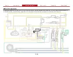
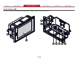
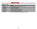
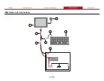
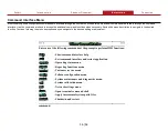
HMI Cables and Connections
Feature
Feature
Description
Description
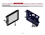
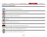
1 Tellurus HMI display
This displays system operation and provides operator control of the system.
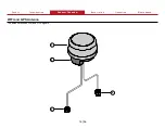
2 Antenna
This transmits and/or receives WiFi and GPS signals.
3 HMI cable
This connect the HMI to power and to the HMI M12 cable.
4 HMI M12 cable
This connect the HMI cable to the control box.
5 Control box
This connects to various components in the system and contains the programmable logic controllers (PLC).
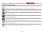
6 Terminating resistor
This terminates the CANbus signal.
7 HMI power cable
This is the installer-supplied power cable. Refer to
for pin-out configuration.
8 System power
This is the system power.
Summary of Contents for AQUIS ULTRAFLOW
Page 2: ......
Page 55: ...Notes 55 56...


