


18
|
56
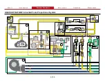
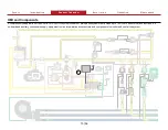
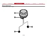
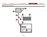
HMI Cable
This cable connects the HMI to the control box and to system power. The power connector, associated connector components, and wiring are installer provided.
Use the table to determine pin location.
2
1
6
9
8
11
7
10
3
4
5
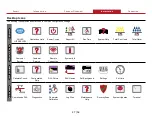
Feature
Feature
Description
Description
1 Deutsch connector
This connects to the Tellurus display—Deutsch DT06-12SB.
2 Deutsch connector
This connects to apparatus power—DT04-6P-E003.
3 Deutsch connector
This connects to the Y-splitter receptacle.
4 Y-splitter receptacle
This connects to the display extension cable.
5 Terminating resistor
This is installed into the receptacle.
6 Pin 6
CAN 2 high, yellow—optional CANbus
7 Pin 5
Term 15, white +12V—back light power
8 Pin 4
+12V, red—power
9 Pin 3
CAN 2 low, green—optional CANbus
10 Pin 2
Ground 2, black
11 Pin 1
Ground, black
Note:
Pin 3 and pin 6 are only connected when the second CANbus option is used.
Summary of Contents for AQUIS ULTRAFLOW
Page 2: ......
Page 55: ...Notes 55 56...


