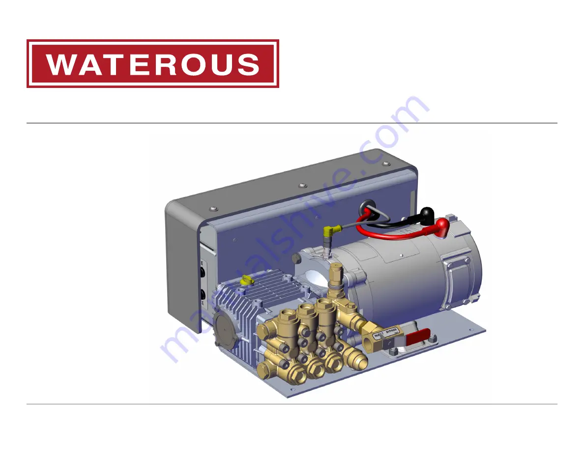
Waterous AQUIS 1.5 Installation, Operation And Maintenance Instructions Download Page 1

AQUIS™ Foam System

Installation, Operation, and Maintenance Instructions

AQUIS 1.5, AQUIS 3.0, and AQUIS 6.0

Waterous Company • 125 Hardman Avenue South • South Saint Paul, MN 55075 • (651) 450-5000

www.waterousco.com

Form Number: F-1031

Issue Date: Aug 1, 2017

Section: 2447

Revision Date: Sept 16, 2022

Summary of Contents for AQUIS 1.5

Page 1: ...nd Maintenance Instructions AQUIS 1 5 AQUIS 3 0 and AQUIS 6 0 Waterous Company 125 Hardman Avenue South South Saint Paul MN 55075 651 450 5000 www waterousco com Form Number F 1031 Issue Date Aug 1 20...

Page 2: ...Valve 28 Flowmeter 28 Inject Bypass Valve 28 Flowmeter Tee 29 Master Waterway Check Valve 30 Concentrate Injector 30 Drain Port 30 Foam Manifold 31 Concentrate Injector 31 Drain Port 31 Pressure Regul...

Page 3: ...Operating in Normal Mode 55 Starting and Stopping the Pump 55 Adjusting the Mix Percentage 55 Operating in Manual Mode 55 Enabling Manual Mode 55 Operating and Disabling Manual Mode 56 Auto Run Mode I...

Page 4: ...perform required procedures proper installation is the responsibility of the purchaser Do not operate the equipment when safety guards are removed Do not modify the equipment Regularly check for leak...

Page 5: ...ong fuse may damage the equipment Equipment Damage Do not touch the surface during operation allow it to cool after operating Hot surface can burn you Hot Surface NOTICE Modifying the equipment can da...

Page 6: ...Disconnect the power before servicing the pump Current can cause serious injury or death High Current Do not operate beyond recommended pressure Liquid ejected at high pressure can cause serious inju...

Page 7: ...al precautions and alert symbols that are in this document Introduction This section is an overview of the document Product Overview This section describes the parts and associated components that mak...

Page 8: ...Meter 3 Meter 3 Meter 3 Meter 3 Meter 3 Meter X Tank Level Switch 2 wire 4 Meter 4 Meter 4 Meter 4 Meter 4 Meter 4 Meter X Foam Tee Foam Tee or or Manifold Manifold Tee with Flowmeter Standard Standar...

Page 9: ...es Rating panel plate This panel plate displays the foam system rating and performance Yes Yes System schematic panel plate This panel plate displays a schematic of the foam system components Yes No F...

Page 10: ...10 64 Safety Introduction Product Overview Installation Operation Maintenance Troubleshooting AQUIS 1 5 Components 1 6 5 3 2 4 7 8 10 9 Figure 1...

Page 11: ...nd terminal strip 3 Pump This is the pump assembly 4 Vented oil cap This is cap replaces the shipping cap 5 Motor This operates the pump 6 Product sensor This senses the pump speed 7 Pump outlet This...

Page 12: ...12 64 Safety Introduction Product Overview Installation Operation Maintenance Troubleshooting AQUIS 3 0 Components 1 5 6 3 2 4 7 8 10 9 Figure 2...

Page 13: ...nd terminal strip 3 Vented oil cap This is cap replaces the shipping cap 4 Pump This is the pump assembly 5 Motor This operates the pump 6 Product sensor This senses the pump speed 7 Pump inlet This i...

Page 14: ...14 64 Safety Introduction Product Overview Installation Operation Maintenance Troubleshooting AQUIS 1 5 and 3 0 Under the Cover 1 3 6 4 2 7 5 Figure 3...

Page 15: ...l strip This connects accessories to the control box 2 Circuit breaker This prevents over current 3 Control box This houses the electric components 4 Flowmeter connection This connects control box to...

Page 16: ...16 64 Safety Introduction Product Overview Installation Operation Maintenance Troubleshooting AQUIS 6 0 Components 1 5 6 3 2 4 7 8 10 9 Figure 4...

Page 17: ...nd terminal strip 3 Pump This is the pump assembly 4 Vented oil cap This is cap replaces the shipping cap 5 Motor This operates the pump 6 Product sensor This senses the pump speed 7 Pump outlet This...

Page 18: ...18 64 Safety Introduction Product Overview Installation Operation Maintenance Troubleshooting AQUIS 6 0 Under the Cover 5 6 7 4 3 1 2 Figure 5...

Page 19: ...rip This connects accessories to the control box 2 Fuse housing This is the fuse location 3 Circuit breaker This prevents over current 4 HMI OIT connection This connects the controller to the HMI or O...

Page 20: ...ance Troubleshooting Overview Diagram Typical Note The graphics in this illustration are intended to help you understand concepts in next sections Do not use them to determine physical attributes plac...

Page 21: ...itting with strainer The wye fitting with strainer traps debris that is in the concentrate 9 Foam pump The foam pump transfers pressurized concentrate from the supply tank into the waterway 10 Inject...

Page 22: ...ubleshooting Dual Tank System Overview Optional 6 5 3 1 7 8 9 10 11 12 4 14 13 16 15 21 20 19 18 17 22 2 23 Note The graphics in this illustration are intended to help you understand concepts in next...

Page 23: ...9 Tank B shutoff valve The tank B shutoff valve stops the concentrate from flowing into the supply hose 10 Tank B supply hose This hose supplies concentrate between tank B supply and the electric val...

Page 24: ...24 64 Safety Introduction Product Overview Installation Operation Maintenance Troubleshooting Flush System Overview Optional 4 1 3 2 5 6...

Page 25: ...rmation Component Accessory Component Accessory Description Description 1 Foam pump The foam pump transfers pressurized concentrate from the supply tank into the injector 2 Supply tank The supply tank...

Page 26: ...ts in the system Bypass Hose The bypass hose routes the concentrate from the inject bypass valve to outside the apparatus Pump Mounting Hardware The mounting hardware is required to secure the pump as...

Page 27: ...s for information about obtaining a sensor Horizontal Sensor Vertical Sensor Figure 6 Figure 7 Supply Tank Level Sensor Cable This cable connects the level sensor to the control box It is 2 bare wires...

Page 28: ...NPT Figure 10 Flowmeter The flowmeter paddlewheels measure the amount of water flowing Figure 11 The flowmeter is installed in the flowmeter tee or foam manifold 2 1 3 1 Flowmeter 2 Cable 3 Paddlewhee...

Page 29: ...erway supply line Figure 13 2 1 1 Flowmeter 2 Tee body Figure 13 The flowmeter tee is available in the following configurations 2 inch tee 2 inch tee Inlet Outlet Combination Victaulic 2 inches and FN...

Page 30: ...1 1 2 inches 2 inch valve 2 inch valve Inlet Victaulic 2 inches Victaulic 2 inches Outlet Victaulic 2 inches FNPT 2 inches 2 1 2 inch valve 2 1 2 inch valve Inlet Victaulic 2 1 2 inches Victaulic 2 1...

Page 31: ...Outlet 2 1 2 inches Waterous 4 bolt flange 4 3 8 B C Combination Victaulic 2 inches and FNPT 1 1 2 inches Combination Victaulic 2 1 2 inches and FNPT 2 inches Combination Victaulic 3 inches and FNPT...

Page 32: ...side of the pump to the input side of the pump Do not operate beyond recommended pressure Liquid ejected at high pressure can cause serious injury High Pressure Do not tamper with the pressure regula...

Page 33: ...ation of water flow rate LED displayed warning of low concentrate supply Indicating light for A and B tank when dual supply tanks are installed Manual operating mode for backup Figure 21 Manual OIT Th...

Page 34: ...other to terminal 5 or 8 This sensor alerts you when the concentrate reaches a predetermined level 3 Tank level sensor tank A Connect one wire from the level sensor that is in tank A to terminal 3 and...

Page 35: ...ge electronic components Disconnect all ground wire connections before jumping or welding High Current Avoid damaging the electronics in the control box Disconnect the frame ground before jump startin...

Page 36: ...am tank into the booster tank When specifying an integrated foam tank ensure that you include the installation of the optional low tank level sensor as well as the foam suction connections and tank dr...

Page 37: ...the mounting bracket Locating the OIT Mounting Holes Locate and drill the mounting and opening holes for the OIT Installing the Pump Assembly The foam system components are designed to operate as inst...

Page 38: ...Figure 25 Figure 25 5 Use the included hardware digital OIT or locally source the appropriate hardware manual OIT to secure the OIT to the panel 6 Route the cable to the control box 7 Connect the cabl...

Page 39: ...nsion 4 Install the cover Refer to Installing the Cover on page 45 Installing the Master Waterway Check Valve Note Refer to Overview Diagram Typical on page 20 for the instructions in this section 1 2...

Page 40: ...amage it 4 Route the cable to the control box 5 3 meter M12 4 pin extension cable Connect the cable to the control box Refer to Connecting M12 Cables to the Control Box on page 38 Installing the Flowm...

Page 41: ...jector Refer to the Overview Diagram Typical on page 20 for the instructions in this section The hose is required to meet the following specifications Minimum 3 8 inch inside diameter AQUIS 1 5 and AQ...

Page 42: ...tements before continuing The pump motor uses 30 A to 100 A of current to operate Electrical current is dangerous and can cause serious injury or death Do not attempt to connect the pump motor to the...

Page 43: ...t 20 ft 25 ft 25 ft 30 ft 30 ft Amps Amps 30 A 30 A 12 AWG 10 AWG 8 AWG 8 AWG 6 AWG 50 A 50 A 8 AWG 8 AWG 6 AWG 4 AWG 4 AWG 80 A 80 A 6 AWG 6 AWG 4 AWG 2 AWG 2 AWG Important The foam pump requires a f...

Page 44: ...re the excess cable into a flat loop Figure 27 Note Use the previous instructions to install a second tank level sensor to the controller Connect the wires from the sensor to terminals 2 and 8 on the...

Page 45: ...into the injector fitting in the proper orientation Installing the Cover 1 Locate the 3 screws and washers that you removed from the cover 2 Use the 3 screws and washers to secure the cover to the bra...

Page 46: ...5 0 6 0 6 0 7 0 7 0 8 0 8 0 9 0 9 1 0 1 0 Flow rate Flow rate US gallons US gallons 100 100 0 1 0 2 0 3 0 4 0 5 0 6 0 7 0 8 0 9 1 0 200 200 0 2 0 4 0 6 0 8 1 0 1 2 1 4 1 6 1 8 2 0 300 300 0 3 0 6 0 9...

Page 47: ...Press the SELECT button to select the displayed value 6 Press the FOAM button to save the value and exit the calibration and setup mode Editing the Units of Measure F2 1 Enter the calibration setup mo...

Page 48: ...ured and the displayed value do not match press or up or down button to adjust the display value to match the value that you measured When the low flow value is displayed an insufficient amount of wat...

Page 49: ...oam The proportioning value for this setting is between 0 1 to 1 0 3 0 or 6 0 for both tanks 5 Press the SELECT button to return to the F5 parameter 6 Press the FOAM button to save the value and exit...

Page 50: ...ton to display the zero flow 16 Press the SELECT button to save the value 17 Press the FOAM button to save the value and exit the calibration and setup mode Setting Default Mix Percent for B Foam F7 1...

Page 51: ...iquid Certain operating conditions cause the solution temperature to reach and exceed 160 F 71 C Do not operate if the water temperature exceeds 160 F 71 C Hot liquid can scald you Hot Liquid Avoid co...

Page 52: ...centrate injected into the waterway 2 Blue LED The blue LED indicates the modes and status of the pump operation 3 Red LED The red LED indicates the modes and status of the pump operation 4 ON OFF but...

Page 53: ...ure can cause serious injury High Pressure Do not operate while all discharges or drains are closed High pressure results and damages the foam system its components 1 Press and hold the ON OFF button...

Page 54: ...e value for the current mode 4 Supply tank LED The supply tank LED shows the concentrate tank that is in operation 5 Increase button This button increases the value in the display 6 SELECT button This...

Page 55: ...ntrate into the waterway Adjusting the Mix Percentage 3 Press the SELECT button until the PERCENT LED illuminates 4 Press the up button to increase the percent by 0 1 5 Press the down button to decrea...

Page 56: ...e 1 Press the SELECT button to scroll though the following modes WATER FLOW PERCENT TOTAL WATER TOTAL FOAM and then back to WATER FLOW 2 Press and hold the SELECT button for 3 seconds to lock the disp...

Page 57: ...t Waterous for more information Flushing the Foam System NOTICE Not following maintenance procedures can damage your equipment Perform all maintenance procedures as required Maintenance Leaving corros...

Page 58: ...the Oil Level 1 Locate the oil level window to determine the oil level Figure 1 Figure 2 and Figure 4 2 Ensure that the oil level is centered in the window 3 Add oil if necessary Refer to Adding Oil o...

Page 59: ...2 and Figure 4 2 Use the chart below to determine the oil capacity of your model Model Model Oil Capacity Oil Capacity AQUIS 1 5 AQUIS 1 5 6 1 oz 0 18 L AQUIS 3 0 AQUIS 3 0 10 8 oz 0 32 L AQUIS 6 0 AQ...

Page 60: ...ed fuse rating Using the wrong fuse may damage the equipment Equipment Damage Do not replace the fuse with a value different than specified Doing so causes poor performance or damages the foam system...

Page 61: ...47 1 2 3 1 Wye fitting 2 Strainer 3 Cap Figure 47 5 Remove the strainer from the wye fitting 6 Flush the debris from the stainer 7 Insert the strainer into the wye fitting 8 Secure the cap to the wye...

Page 62: ...concentrate is being injected into the solution The speed sensor is misaligned or out of adjustment Check the alignment of the speed sensor The flowmeter is out of calibration Calibrate the flowmeter...

Page 63: ...OIT is illuminated The concentrate supply tank is empty Add concentrate to the tank The concentrate tank level switch is malfunctioning Repair or replace the switch or cable The mix does not output fr...

Page 64: ...Waterous Company 125 Hardman Avenue South South Saint Paul MN 55075 651 450 5000 www waterousco com...

Reviews: