


43
Finish 270 / 250
GB
8.1
cleAnInG tHe unIt FROM tHe OutSIde
First unplug the power plug from the outlet.
Danger of short-circuits caused by water
ingression! Never spray down the unit with
high-pressure or high-pressure steam clea-
ners.
Wipe down unit externally with a cloth which has been im-
mersed in a suitable cleaning agent.
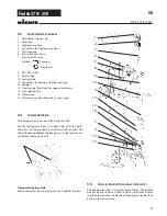
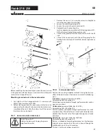
8.2
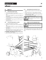
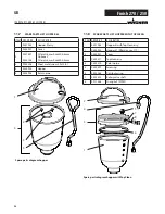
SuctIOn FIlteR
Clean filters always ensure maximum volume,
constant spray pressure and problem-free
functioning of the unit.
Unit with suction system
1. Unscrew the filter (Item 1) from the suction tube.
2. Clean or replace the filter.
Carry out cleaning with a hard brush and a corresponding
cleaning agent.
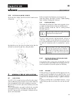
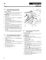
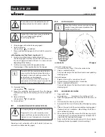
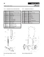
8.3
HIGH-PReSSuRe FIlteR
1. Open relief valve
valve position
(circulation) - Switch the unit off.
2. Open the high-pressure filter and clean the filter insert. To
do so:
3. Unscrew the filter housing (1) by hand.
4. Remove the filter insert (2) and pull out the bearing spring
(3).
5. Clean all the parts with the corresponding cleaning agent.
If compressed air is available – blow through the filter in-
sert and bearing spring.
6. When mounting the filter ensure that the bearing ring (4)
in the filter insert is positioned correctly and check the O-
ring at the filter housing for damage.
7. Screw on the filter housing by hand until it stops (a higher
tightening force only impedes later dismantling).
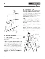
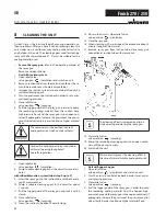
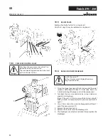
cleanIng the unIt
The container must be earthed in case of
coating materials which contain solvents.
Caution! Do not pump or spray in container
with small opening (bunghole)!
See safty regulations.
5. Fill up hopper with suitable cleaning agent.
6. Open relief valve
valve position
(circulation)
7. Pump suitable cleaning agent in the circuit for several mi-
nutes.
with cleaning ring (topclean) step 8 up to 12
8. Switch reverser knob into a horizontal position.
The cleaning agent will flow around the circumference of
the inner hopper wall and will clean it in some minutes,
depending of the fouling
9. Switch reverser knob into the upright position.
Cleaning agent is flowing directly into the hopper
Do not switch the reverser knob at the clea-
ning ring into the horizontal position when
the pump is load with coating material. The
devider holes can be plugged.
Than the cleaning work of cleaning ring is
reduced, and it will take more time up to the
cleaning ring has cleaned themself.
10. Close relief valve,
valve position
(spraying)
11. Pump the remaining cleaning agent from the hopper,
high-pressure hose and the spray gun into an open con-
tainer
12. Open relief valve
valve position
(circulation)
13. Switch off unit
1
2
suction tube
5l hopper
Unit with hopper
1. Release screws with a screwdriver (Item 2).
2. Lift and remove filter disk with a screwdriver
3. Clean or replace the filter disk.
Carry out cleaning with a hard brush and a corresponding
cleaning agent.
Summary of Contents for Finish 250
Page 19: ...19 Finish 270 250 10 9 Schaltplan d reparaturen am ger t...
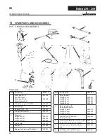
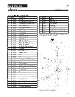
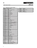
Page 24: ...24 Finish 270 250 ersatzteile und zubeh r Ersatzteilbild Pumpenaggregat d...
Page 48: ...48 Finish 270 250 GB Repairs at the unit 10 9 Connection diagram...
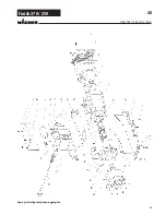
Page 53: ...53 Finish 270 250 GB Spare parts diagram pump aggregate Spare parts and accessories...
Page 77: ...77 Finish 270 250 10 9 Sch ma lectrique F R parations sur l appareil...
Page 107: ...107 Finish 270 250 10 9 Elektrisch schema Reparaties aan het apparaat NL...
Page 112: ...112 Finish 270 250 Onderdelenafbeelding pompaggregaat NL Accessoires en onderdelen...
Page 118: ...118 Finish 270 250 NL CE Verklaring van overeenstemming...
Page 119: ...119 Finish 270 250 NL CE Verklaring van overeenstemming...


