


40
Finish 270 / 250
GB
startup
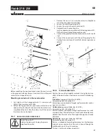
4.5
cleAnInG PReSeRVInG AGent WHen
StARtInG-uP OF OPeRAtIOn InItIAlly
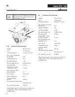
unit with suction tube
1. Immerse the suction system into a container filled with a
suitable cleaning agent (recommendation: water).
unit with hopper
2. fill up hopper with a suitable cleaning agent (recommen-
dation: water).
3. Switch on unit.
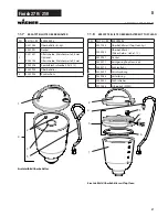
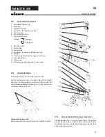
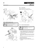
4. Turn the pressure regulating knob (1) to the
right
until
the stop is reached.
5. Open relief valve (2)
valve position
(circulation)
6. Wait until cleaning agent is emitted from the return hose.
7. Turn the pressure regulating knob (1) back approx. one
rotation.
8. Close relief valve (2)
valve position
(spraying), pressure is rising up inside
the high pressure hose (visble at pressure gage)
9. Point the tip of the spray gun into an open collecting con-
tainer and pull the trigger guard at the spray gun.
10. The pressure is increased by turning the pressure regula-
ting knob (1) to the right. Set approx. 10 MPa at the pres-
sure gage.
11. Spray the cleaning agent out of the unit for approx.
1 - 2 min. (~5 liters) into the open collecting container.
4.7
tAkInG tHe unIt IntO OPeRAtIOn WItH
cOAtInG MAteRIAl
unit with suction tube
1. Immerse the suction system into a container filled with
coating material.
unit with hopper
2. fill coating material into the hopper.
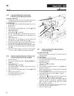
3. Press inlet valve pusher (4) several times to release possib-
ly clogged inlet valve
4. Open relief valve (2)
valve position
(circulation)
5. Switch on unit.
6. Turn the pressure regulating knob (1) to the
right
until
the stop is reached.
When the noise of the valves changes, the unit is bled and
takes in coating material.
7. If coating material exits from the return hose, turn the
pressure regulating knob (1) back approx. 1 rotation.
8. Close relief valve (2)
valve position
(spraying), pressure is rising up inside
the high pressure hose (visble at pressure gage)
9. Pull of the spray gun and spray into an open collecting
container in order to remove the remaining cleaning
agent from the unit. When coating materials exits from
the tip, close the spray gun.
10. Pull of the spray gun and adjust the spraying pressure by
turning the pressure regulating knob (1).
11. The unit is ready to spray.
4.6
VentIlAte unIt (HydRAulIc SySteM) IF tHe
SOund OF Inlet VAlVe IS nOt AudIBle
1. Switch on the unit.
2. Turn pressure regulating knob (1)
three revolutions
to
the
left
.
3. Open relief valve (2)
valve position
(circulation)
The hydraulic system is ventilated. Leave the unit on for
two or three minutes.
4. Then turn pressure regulating knob (1) to the
right
until
stop.
5. Press inlet valve pusher (4).
Sound of the inlet valve is audible.
6. If not, repeat points 2 and 4
1
2
3
4
Summary of Contents for Finish 250
Page 19: ...19 Finish 270 250 10 9 Schaltplan d reparaturen am ger t...
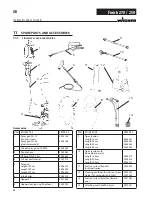
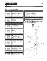
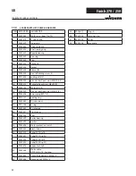
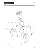
Page 24: ...24 Finish 270 250 ersatzteile und zubeh r Ersatzteilbild Pumpenaggregat d...
Page 48: ...48 Finish 270 250 GB Repairs at the unit 10 9 Connection diagram...
Page 53: ...53 Finish 270 250 GB Spare parts diagram pump aggregate Spare parts and accessories...
Page 77: ...77 Finish 270 250 10 9 Sch ma lectrique F R parations sur l appareil...
Page 107: ...107 Finish 270 250 10 9 Elektrisch schema Reparaties aan het apparaat NL...
Page 112: ...112 Finish 270 250 Onderdelenafbeelding pompaggregaat NL Accessoires en onderdelen...
Page 118: ...118 Finish 270 250 NL CE Verklaring van overeenstemming...
Page 119: ...119 Finish 270 250 NL CE Verklaring van overeenstemming...


