English
•
Filling with UV additive
•
Filling of refrigerant
After each process has been performed a service report is printed. Subsequent actions are only initiated once the
preceding action has been completed successfully.
1.
Fit the service hoses for the A/C service unit to the vehicle air conditioning system, and open the service
couplings.
2.
Press the cursor key or to acces the basic menu.
3.
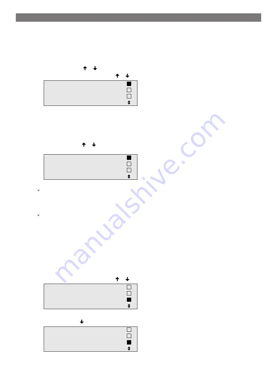
In the basic menu use the cursor keys or to select
Short selection
.
Short selection
Free selection
Other selections
ENTER-OK
4.
Press
ENTER
to confirm.
5.
Use the keypad and the cursor keys to enter the vehicle data.
6.
Press
ENTER
to confirm.
7.
Enter the refrigerant filling quantity. Use the value shown on the filling quantities sticker in the vehicle and
enter it using the keypad and the cursor keys and press
ENTER
.
8.
Use the cursor keys or to select whether the air conditioning system has two connections (high pres-
sure and low pressure) or only one connection (high pressure or low pressure).
HP/LP
PORT
HP
PORT
LP
PORT
ENTER-OK STOP-EXIT
9.
Press
ENTER
to confirm.
The fully automatic air conditioning service is started.
After the air conditioning service has finished, you will be prompted to disconnect the A/C service unit's ser-
vice hoses of from the vehicle air conditioning system.
10.
Disconnect the service hoses and press
ENTER
to confirm.
The service hoses will now be drained. The A/C service unit is then ready for further use.
11.
Put the valve caps of the vehicle air conditioning system back on the connections.
13.3 User Codes
It is possible to protect the A/C service unit from unauthorised access using personal user codes. When this func-
tion is activated, the system queries the user code after being switched on, and the A/C service unit cannot be
started without it. Up to 10 different users can be created with individual codes. Users can be created using the
administrator code.
13.3.1 Creating user codes
1.
In the basic menu use the cursor keys or to select
Other selections
.
Short selection
Free selection
Other selections
ENTER-OK
2.
Press
ENTER
to confirm.
3.
Use the cursor key to select
Service
and press
ENTER
to confirm.
Flushing
Reset scales.
Service.
ENTER-OK STOP-EXIT
14
Summary of Contents for AirCon ASC 6100G
Page 33: ...English 17 1 Flowchart ASC6100 G Legend 31...
Page 36: ...English 17 2 Circuit diagram ASC6100 G 34...
Page 37: ...English 35...
Page 70: ...French 17 1 Organigramme ASC6100 G L gende 68...
Page 73: ...French 17 2 Sch ma lectrique ASC6100 G 71...
Page 74: ...French 72...
Page 107: ...German 17 1 Flussdiagramm ASC6100 G Legende 105...
Page 110: ...German 17 2 Schaltplan ASC6100 G 108...
Page 111: ...German 109...
Page 113: ...4 4 Tel 49 0 2572 879 0 5 6 Domestic 111...
Page 114: ...Russian 6 1 112...
Page 115: ...Russian 6 2 R1234yf 405 C R134a 743 C R153A 6 3 113...
Page 117: ...10 Dometic 10 10 1 230 V 50 Hz 10 2 10 3 10 4 115...
Page 118: ...11 11 1 2 3 4 5 6 7 USB 116...
Page 119: ...Russian 8 9 10 11 12 117...
Page 124: ...Russian 12 8 8 9 10 12 9 12 2000 g 1 STOP 2 R R1234yf L liquid 122...
Page 137: ...Russian 10 ENTER 11 12 ENTER 13 14 15 D 16 E 17 15 Nm 18 19 20 R1234yf 133 21 133 14 4 135...
Page 139: ...Russian 2 D E 3 I 4 G 5 J 6 J 7 H G 8 9 10 133 14 6 1 2 7783 3 137...
Page 142: ...15 15 ENTER 8 min 50 mbar 120 mbar 134 ENTER 3 136 140...
Page 145: ...Russian 17 1 ASC6100 G 143...
Page 147: ...Russian V1 V2 V3 NCG V4 VC XP XP X3 UV 145...
Page 148: ...Russian 17 2 ASC6100 G 146...
Page 149: ...Russian 147...
Page 183: ...Spanish 17 1 Diagrama de flujo ASC6100 G Leyenda 181...
Page 186: ...Spanish 17 2 Esquema de conexiones ASC6100 G 184...
Page 187: ...Spanish 185...
Page 188: ...4445103553 2022 05 10...


