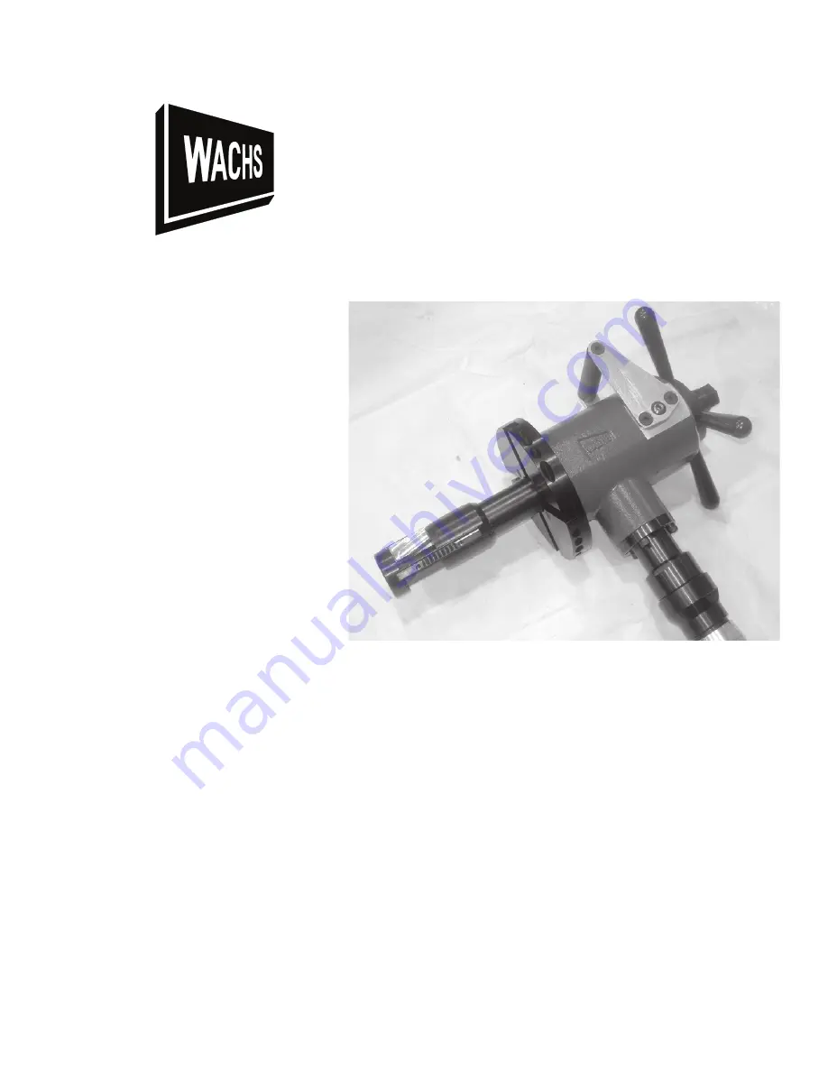
Wachs SDB 206 User Manual Download Page 1


SDB 206 and FF 313

User’s Manual

Copyright © 2013 E.H. Wachs. All rights reserved.

This manual may not be reproduced in whole or in part

without the written consent of E.H. Wachs.

E.H. Wachs

600 Knightsbridge Parkway

Lincolnshire, IL  60069

www.ehwachs.com

E.H. Wachs Part No. 56-MAN-01

Revision B

September 2013

Summary of Contents for SDB 206

Page 1: ...H Wachs All rights reserved This manual may not be reproduced in whole or in part without the written consent of E H Wachs E H Wachs 600 Knightsbridge Parkway Lincolnshire IL 60069 www ehwachs com E H...

Page 2: ...arkway Lincolnshire IL 60069 USA Responsible Representative Orbitalum Tools GmbH Josef Sch ttler Str 17 78224 Singen Germany Tel 49 0 7731 792 872 Fax 49 0 7731 792 566 Harmonised Standards Other Tech...

Page 3: ...ipe or tube with wall thickness up to 0 75 The machine clamps to the I D of the pipe being machined using a three leg mandrel design for square rigid installa tion Different sized clamp legs are used...

Page 4: ...you can easily move the machine from one pipe to the next with no additional setup required Three different sized rotating heads and four styles of man drels are available with the SDB 206 The three r...

Page 5: ...Figure 1 4 The feed drive includes a four post handle and a gauge for measuring feed distance Clamping Legs The standard chuck legs built into the mandrel allow an I D clamping range of 2 27 to 2 92 S...

Page 6: ...O D s over 6 you will need to install the optional 8 diameter head 56 076 00 Table 2 Extended Range Leg Sets Part No Leg Thickness Pipe I D Range 56 085 08 2 22 6 71 7 34 56 085 09 2 51 7 28 7 91 56...

Page 7: ...each leg set Each leg has two captivated mounting screws that attach the leg to the chuck leg on the mandrel Figure 1 7 The screws in the clamp leg attach it to the chuck leg on the mandrel Noise Lev...

Page 8: ...r lever Motor speed control Feed rate 0 08 2 mm per revolution Feed stroke 2 5 usable feed travel Drive options Air 70 cfm 90 psi Hydraulic 8 gpm 1500 psi Electric 110 V or 220 V Tool RPM 0 to 40 Tool...

Page 9: ...01 Rev B 7 Operating Envelopes and Tooling Charts This section includes the following information for using the SBD 206 and FF 313 operating envelope for the SDB 206 and FF 313 machine configurations...

Page 10: ...SDB 206 and FF 313 8 Part No 56 MAN 01 Rev B E H Wachs...

Page 11: ...Introduction to the Equipment E H Wachs Part No 56 MAN 01 Rev B 9 SDB 206 Air Drive 56 000 01 DETAIL A NOTE...

Page 12: ...SDB 206 and FF 313 10 Part No 56 MAN 01 Rev B E H Wachs SDB 206 Electric Drive 56 000 02 NOTE...

Page 13: ...Introduction to the Equipment E H Wachs Part No 56 MAN 01 Rev B 11 SDB 206 Hydraulic Drive 56 000 03 NOTE...

Page 14: ...SDB 206 and FF 313 12 Part No 56 MAN 01 Rev B E H Wachs FF 313 Air Drive 56 000 FF DIMENSIONS IN BRACKETS ARE MILLIMETERS...

Page 15: ...Introduction to the Equipment E H Wachs Part No 56 MAN 01 Rev B 13 Standard Mandrel and Extension Legs 56 430 00 DIMENSIONS IN BRACKETS ARE MILLIMETERS NOTE...

Page 16: ...08 02 37 1 2 30 30 0 73 18 5mm 1 50 38 1mm 0 53 13 5mm 3 03 77 0mm 2 26 57 4mm 3 48 88 4mm 6 18 157 0mm 4 88 124 0mm 6 60 167 6mm 7 84 199 1mm 7 84 199 1mm 7 60 193 0mm Counterbore Tool Chart PIPE I D...

Page 17: ...CING TOOL MAX WALL W 1 16 LAND MIN I D W 1 16 LAND MAX I D 1 W 1 16 LAND MAX O D 1 56 709 01 56 708 01 1 68 42 7mm 2 38 60 5mm 5 00 127 0mm 8 09 205 5mm 56 709 05 56 708 01 1 68 42 7mm 2 38 60 5mm 6 2...

Page 18: ...SDB 206 and FF 313 16 Part No 56 MAN 01 Rev B E H Wachs...

Page 19: ...uts leak ing lubricant rusted components and any other physi cal conditions that may affect operation Properly maintaining the machine can greatly decrease the chances for injury ALWAYS READ STICKERS...

Page 20: ...luding lathe tools saw blades milling tools etc may get very hot Do not touch tooling until you have made sure it is cool enough to handle Wear gloves when removing or cleaning up chips and cutting de...

Page 21: ...D EQUIPMENT Disconnect hydrau lic lines from the hydraulic manifold to prevent acciden tal restarting of the machine Lock out the power supply immediately ELECTRIC POWERED EQUIPMENT If the electric dr...

Page 22: ...hine Gloves can become entangled in moving parts resulting in serious injury Gloves may be worn when setting up the machine or cleaning up after the operation but take them off when operating the mach...

Page 23: ...ration of other tools and equipment in the area reflective surfaces process noises and resonant struc tures can increase the noise level in the area For additional information on hearing protection re...

Page 24: ...en operating the equipment Part no 90 401 03 Figure 2 3 The eye protection label is attached to the hydraulic drive of the SDB 206 FF 313 Always wear eye protection when operating the equipment Part n...

Page 25: ...Do not oper ate the equipment with greater than 2000 psi 138 bar hydraulic pressure Part no 90 402 01 Figure 2 6 The hot surface label is attached to the SDB 206 FF 313 hydraulic and electric drive m...

Page 26: ...SDB 206 and FF 313 24 Part No 56 MAN 01 Rev B E H Wachs...

Page 27: ...se mandrels have three legs which expand equally to contact the inside walls of the workpiece when the draw bolt is tightened Measure the pipe I D that is to be prepared Turn to page six 6 to select t...

Page 28: ...beveling head for dirt and metal chips Clean the bore with compressed air or solvent as necessary Wipe the mandrel clean and apply a light coating of oil Being careful not to scrape the head bushing i...

Page 29: ...it clockwise until the draw bar nut is completely exposed Be certain to align the key in the end cap to the key way of the mandrel Use the two locking set screws located on either side of the machine...

Page 30: ...he Rotating head Refer to Tool Charts for the appropriate tool bit All tool bits must be installed so the cutting edge will contact the pipe when rotating in a clockwise direction as seen from rear of...

Page 31: ...ft lb Figure 3 4 Move the machine back and forth and up and down while tightening The chuck legs will automatically center the machine Connect a clean dry 90 psi 6 bar air supply to machine Start mach...

Page 32: ...d feed in until desired prep is achieved Figure 3 5 Figure 3 5 Tips For Good Finish 1 Always place mandrel as close to pipe end as possible 2 Use a cutting oil or other coolant generously This will al...

Page 33: ...rsion Procedure 1 Remove the mandrel from the machine body 2 Using the provided hex key set remove the Rotating Head by loosening and removing the four 5 16 18 x 3 4 stripper bolts Figure 3 6 Figure 3...

Page 34: ...tightening the four 5 16 18 x 5 8 stripper bolts Figure 3 8 Figure 3 8 5 Install the Flange Facing Mandrel into the flange I D using the alignment fixture to insure proper squareness to flange Once th...

Page 35: ...he flange I D Refer to mandrel leg extension chart To select the mandrel adaptor and leg Set required to mount in flange I D 2 Insert the solid leg set 56 135 12 in the mandrel head POINT SIDE DOWN Fi...

Page 36: ...the selected adapter over the mandrel head and secure with 3 7 16 20 x 1 1 2 SHCS Figure 3 11 Figure 3 11 4 Select extension leg set required Refer to the I D range chart decal provided on the leg ex...

Page 37: ...e adjustable leg and tighten completely Figure 3 13 Figure 3 13 ABOUT THE ADJUSTABLE LEG An adjustable leg has been provided to compensate for centering on slip over flanges or butt welded flanges whe...

Page 38: ...to perform the desired operation Snug the mandrel into place by tightening the draw bar nut with the supplied 1 1 8 wrench Figure 3 15 NOTE Observe the mandrel keyway slots When the slots are at the...

Page 39: ...p Operation E H Wachs Part No 56 MAN 01 Rev B 37 8 Slide the flange alignment fixture over the mandrel shaft Figure 3 16 Figure 3 16 9 Extend the alignment arms if necessary with the supplied hex key...

Page 40: ...e draw bar nut and push the alignment fixture firmly against the flange face Retighten the draw bar nut with the supplied 1 1 8 wrench Figure 18 Remove alignment fixture NOTE The alignment fixture aut...

Page 41: ...haft Be sure to wipe the mandrel clean NOTE Align the internal machine keys with the mandrel keyway slots Engage the internal machine keys on the mandrel keyway slots Push the machine forward Rotate t...

Page 42: ...Rev B E H Wachs 12 Install the tooling in to the flange facer tool slide slot Figure 3 20 Refer to the tool holder tool bit diagram Figure 3 20 13 Tighten the tool bit locking set screws with the supp...

Page 43: ...supply Press the air motor lever and rotate the machine slowly to verify clear ance Figure 3 23 IMPORTANT E H Wachs Co recommends the use of an ATM air treatment module pn 26 407 00 to filter air and...

Page 44: ...e counter clockwise rotation will close the valve Figure 3 23 Figure 3 23 16 Rotate the starwheel nut with the supplied 3 4 socket and ratchet Figure 3 24 until the tool bit tip is flush with the desi...

Page 45: ...assembly clockwise until the tool bit just touches the desired surface to be faced 18 Again rotate the tool slide starwheel nut raising the bit just above the surface to be faced 19 Using the infeed...

Page 46: ...e 3 27 Figure 3 27 21 Engage the desired number of trips on the trip collar assembly to achieve the surface finish required Figure 3 28 Refer to flange surface trip chart Figure 3 28 NOTE Take light c...

Page 47: ...f variables inherent in a portable machine of this type 4 INTERMITTENT CUTS When working on a rough cut end of a piece of pipe or a warped flange tou will need to do an intermittened cut In order to p...

Page 48: ...tating the axial feed handle counterclockwise The correct amount of axial feed per machine revolution is given on the following chart TRIP ENGAGEMENT RMS FINISH 1 TRIP 63 RMS 2 TRIP 125 RMS 4 TRIP 250...

Page 49: ...tab clear from the locknut 56 033 00 Insert and tighten an old used tool bit into one of the slots on the cutting head Clamp machine into a bench vise Using the lock nut tool and a torque wrench tight...

Page 50: ...e machine body and inspected after every twenty hours of operation 2 Remove the drawbar nut 56 025 00 and the collar nut 56 024 00 3 Remove the mandrel from the machine body by rotating the feed handl...

Page 51: ...Parts Lists and Drawings E H Wachs Part No 56 MAN 01 Rev B 49 PARTS LISTS AND DRAWINGS SDB 206 Air Drive 56 000 01 NOTES ITEM PART NUMBER QTY DESCRIPTION...

Page 52: ...SDB 206 and FF 313 50 Part No 56 MAN 01 Rev B E H Wachs SDB 206 110 V Electric 56 000 02 NOTES ITEM PART NUMBER QTY DESCRIPTION...

Page 53: ...Parts Lists and Drawings E H Wachs Part No 56 MAN 01 Rev B 51 SDB 206 Hydraulic Drive 56 000 03 NOTES ITEM PART NUMBER QTY DESCRIPTION...

Page 54: ...SDB 206 and FF 313 52 Part No 56 MAN 01 Rev B E H Wachs SDB 206 220 V Electric 56 000 04 NOTES ITEM PART NUMBER QTY DESCRIPTION...

Page 55: ...Parts Lists and Drawings E H Wachs Part No 56 MAN 01 Rev B 53 FF 313 Flange Facer 56 000 FF NOTES ITEM PART NUMBER QTY DESCRIPTION...

Page 56: ...6 182 00 2 KEY 8 56 183 00 2 STRAP 9 56 184 00 2 SCREW KEY ADJUSTABLE 10 56 185 00 2 BUSHING ADJUSTABLE SCREW 11 56 186 00 2 BRACKET HANDLE 12 56 187 00 1 HANDLE LIFTING 13 56 189 00 1 LABEL FEED RING...

Page 57: ...2 26 047 00 1 NAME PLATE 3 56 001 00 1 BODY MAIN 4 56 003 00 1 SHAFT MAIN 5 56 008 00 1 GEAR RING 6 56 009 00 1 GEAR PINION 7 56 029 00 1 BEARING CONE 8 56 030 00 1 BEARING CUP 9 56 031 00 1 BEARING C...

Page 58: ...56 430 02 1 STANDARD RANGE LEG KIT 2 72 6 79 ID Standard Mandrel 56 430 01 7 9 6 3 8 4 1 5 2 ITEM PART NUMBER QTY DESCRIPTION 1 56 024 02 1 COLLAR DRAWBAR NUT 2 56 025 00 1 NUT DRAWBAR 3 56 026 00 1...

Page 59: ...85 03 3 LEG EXTENSION ASSEMBLY 03 4 56 085 04 3 LEG EXTENSION ASSEMBLY 04 5 56 085 05 3 LEG EXTENSION ASSEMBLY 05 6 56 085 06 3 LEG EXTENSION ASSEMBLY 06 7 56 085 07 3 LEG EXTENSION ASSEMBLY 07 Leg Se...

Page 60: ...01 2 72 3 39 69 1 86 0 mm DESCRIPTION TABLE LHCS 1 4 20 X 1 2 CAPTIVATED EXTENSION LEG 02 3 28 3 95 83 4 100 4 mm SHCS 1 4 20 X 5 8 CAPTIVATED SHCS 1 4 20 X 5 8 CAPTIVATED EXTENSION LEG 03 3 85 4 52...

Page 61: ...Parts Lists and Drawings E H Wachs Part No 56 MAN 01 Rev B 59 Small I D Mandrel 56 402 01 NOTES ITEM PART NUMBER QTY DESCRIPTION...

Page 62: ...6 MAN 01 Rev B E H Wachs Fitting Mandrel Assembly 56 414 01 NOTES DIMENSIONS IN BRACKETS ARE MILLIMETERS ITEM PART NUMBER QTY DESCRIPTION MIN MAX DIMENSION A DIA DESCRIPTION QTY PART NO ITEM DESCRIPTI...

Page 63: ...Part No 56 MAN 01 Rev B 61 Mandrel Adapter Assembly 56 415 00 DIMENSIONS IN BRACKETS ARE MILLIMETERS NOTES ITEM PART NUMBER QTY DESCRIPTION WHERE USED ITEM QTY PART NO DESCRIPTION ITEM PART NO QTY DE...

Page 64: ...1 CONE 7 56 136 03 1 LEG ADJUSTABLE 8 56 137 00 1 SCREW ADJUSTABLE 9 56 138 00 1 ROD DRAW 10 56 170 00 1 BODY FIXTURE 11 56 171 00 3 LEG 12 56 188 00 1 MANDREL 13 90 044 03 9 SSS 10 24 X 3 8 14 90 04...

Page 65: ...1 ITEM PART NUMBER QTY DESCRIPTION 1 05 082 00 1 OILER AIR LINE 2 56 044 01 1 AIR MOTOR HIGH TORQUE LOW SPEED 3 66 100 00 1 VALVE FLOW CONTROL 4 90 098 01 1 NIPPLE 1 2 X CLOSE 5 90 098 65 1 1 2 NPT M...

Page 66: ...DEFLECTOR EXHAUST 1 18 CLE 203101 CYLINDER 1 18 1 CLE 863887 PIN SLOTTED SPRING 1 19 CLE 869572 PLATE REAR BEARING 1 20 CLE 843444 BEARING BALL 1 21 CLE 867536 PLATE FRONT BEARING 1 22 CLE 619377 BEA...

Page 67: ...AINING 5 WHERE USED 1 ELECTRIC MOTOR 6 26 126 02 1 COUPLING INPUT 7 56 201 00 1 HOUSING GEAR 8 56 202 00 1 SPACER GEAR SET 9 56 203 00 1 GEAR PLANETARY 10 66 144 00 1 COUPLER DRIVE 11 66 148 00 1 BEAR...

Page 68: ...SPRING TORSION 12 76 075 00 1 PLATE SPRING COVER 13 76 176 00 1 VALVE PRESSURE RELIEF 14 76 177 00 1 VALVE PRESSURE COMPENSATED FLOW CONTROL 15 76 180 00 1 RING 26MM EXT RETAINING 16 76 181 00 1 DETE...

Page 69: ...TOR 2 05 092 00 1 ADAPTOR MOTOR HYD 3 23 187 00 1 MANIFOLD 4 23 188 00 1 FLOW VALVE 5 23 189 00 1 COMPENSATOR SPOOL 6 53 073 00 1 HYDRAULIC MOTOR 7 56 132 00 1 SPACER 8 56 200 00 1 KEY 9 90 054 04 1 S...

Page 70: ...0 1 8 ROTATING HEAD 2 56 430 03 1 EXTENDED RANGE LEG KIT 6 68 9 06 ID Replacement Chuck Body Legs 56 310 00 2 1 5 3 4 ITEM PART NUMBER QTY DESCRIPTION 1 56 026 00 1 BODY CHUCK 2 56 051 00 3 LEG CHUCK...

Page 71: ...HIGH RANGE TOOL HOLDER 17 56 195 00 1 LOW RANGE TOOL HOLDER NOT SHOWN 18 56 710 00 2 TOOL INSERT 19 66 015 00 2 BEARING FEED SCREW 20 66 019 00 1 PLUNGER SPRING 21 66 109 00 1 SUPPORT END 22 66 114 0...

Page 72: ...206 Conv Kit 56 420 00 3 4 1 2 ITEM PART NUMBER QTY DESCRIPTION 1 56 005 00 1 HEAD ROTATING 2 56 043 00 1 WIPER FELT 3 56 430 00 1 SDB 206 MANDREL AND LEG ASSEMBLY 4 90 067 59 4 BOLT STRIPPER 5 16 X 1...

Page 73: ...wings and parts lists in Chapter 8 Please provide the part description and part number for all parts you are ordering Repair Information Please call us for an authorization number before returning any...

Page 74: ...is a warranty card Please fill out the registration card and return to E H Wachs Retain the owner s registration record and warranty card for your information Return Goods Address Return equipment fo...

Page 75: ......

Page 76: ...E H WACHS Superior Equipment Complete Support 600 Knightsbridge Parkway Lincolnshire IL 60069 847 537 8800 www ehwachs com...

Reviews: