14
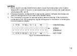
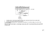
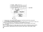
Table 1. Terminal Designation Descriptions.
Terminal Designation
Description
RC (see Note 1)
Power for cooling--connect to secondary side of cooling system 24v
transformer
R (see Note 1)
Power for heating--connect to secondary side of heating system 24v
transformer
C
Common wire from secondary side of 24V transformer
Y
Compressor contactor
G
Fan relay
Y2
Second stage cooling
O/B/W (see Note 2)
Changeover valve for heat pump systems or Heat relay
AUX/W2
Auxiliary heat relay for heat pump systems or Second stage heat relay
E
Emergency heat relay for heat pump systems
L (see note 3)
Equipment alarm monitor for heat pump systems
Summary of Contents for LAKEPRO-1
Page 1: ...LAKEPRO 1 WI FI TOUCHSCREEN PROGRAMMABLE THERMOSTAT...
Page 4: ......
Page 11: ...7 Fig 2 Lakepro 1 rear dimensions in inches mm...
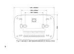
Page 12: ...8 Fig 3 Lakepro 1 wall plate dimensions in inches mm...
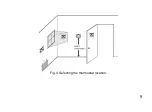
Page 13: ...9 Fig 4 Selecting the thermostat location...
Page 16: ...12 Fig 5 Mounting wall plate...
Page 20: ...16 Fig 7 Inserting wires in terminal block IMPORTANT Use 18 gauge thermostat wire...
Page 68: ...64 Fig 36 Fig 37 6 Wait for the thermostat to be added successfully You may have to press Done...
Page 83: ......


