


56
Use the keyboard or mouse (recommended) to set each field. Ensure each
field is set correctly before clicking
OK
. If parameters are set incorrectly it
could result in the display becoming unreadable and very difficult to correct.
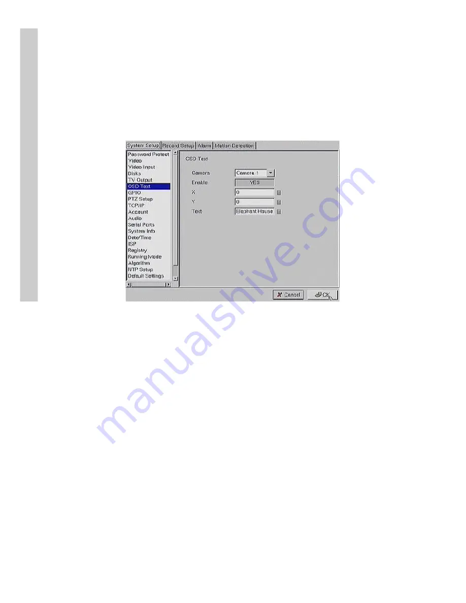
OSD text
Use the
OSD Text
menu to assign text for each of the connected cameras.
For instance, you may like to have text saying “Warehouse” on the image
from a camera installed in the warehouse.
To display the OSD text:
1. Select the desired camera from the
Camera
drop-down box.
2. Click the
Enable
field to display the text.
3. Adjust the position of the text displayed on the image using the
X
and
Y
parameters. A value of X = 0 and Y= 0 would result in the
text appearing at the top left corner of the camera image. Increas
ing the value of Y moves the text down the screen. Increasing the
value of X moves the test to the right. Enter the text to be dis
played in the
Text
field.
4. Use the keyboard or mouse (recommended) to complete the fields
and click
OK
to save changes.
GPIO
The GPIO (general purpose input output) menu enables you to view the
status of the input and output devices such as switches, sensors, LEDs, and
so on and view their status. These devices can be attached to the unit to
turn external alarms (outputs) on or off when the specified input changes.
When an alarm has been triggered, the
GPI
and
GPO
that are connected
will show the status of the input or output device. GPI devices will show
NC
(normally closed) or
NO
(normally open) as the status of the switch.
Setup


