33
ENGLISH
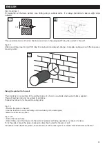
Fig. 18
Complete equipment fixing by pushing it completely against the wall plate and locking it into the upper side by means of
the two corresponding screws.
Fig. 19
After having fixed the plate, you need to fix the two supplied air vents for the ventilation channels on the outside.
To secure the air vents, similarly to the instructions provided above for the plate, simply position in in the hole made, mark
holes and drill.
Fig. 20
One of the two vents is designed to permit nozzle fixing for condensate nebulisation.
The nozzle is equipped with a connector for the tube that connects it to the condensate collection tray.
Fig. 21
The system automatically check the excessive condensate collected at the bottom of the device inside a suitable tray.
1
2
18
18
19
19
Fixing screws for each vent
4
Ø Expected dowel
6 mm
Detail of condensate collection tray
Tray
21
21
Detail of the outside nebuliser
Nebuliser
22
22
20
20
Condensate nebulisation nozzle attachment
Tube connection
with nebuliser
Fig. 22
Once a certain level has been reached, the control system
automatically activates a pump that sends it to the
nebulisation nozzle.


