


Series S34 Instruction Manual
Chapter 6 Troubleshooting and Repair
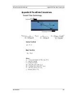
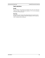
M-000-00030
6-10
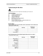
Determine the Fault
Symptom: Output at No Flow
1.
The programming values defined in the
Calibration
menu may not match the
actual hardware being used at the time of measurement, leading to erroneous flow
rate readings. Verify that the programmed values match the hardware that is being
used with the handheld unit.
Symptom: Erratic Output
1.
Mechanical installation may be incorrect. Verify the straight run is adequate as
described in chapter 2 of the manual.
2.
The meter may be reacting to actual changes in the flow stream. The output can
be smoothed using a time constant. The displayed values can be smoothed using
the time constant in the
Display
menu. The analog outputs can be smoothed using
the time constant in the
Output
menu. A time constant of 1 will result in the
change in value reaching 63% of its final value in one second. A time constant of
4 is 22%, 10 is 9.5%, and 50 is 1.9% of the final value in one second. The time
constant equation is shown below (TC= Time Constant).
% 𝑐ℎ𝑎𝑛𝑔𝑒 𝑡𝑜 𝑓𝑖𝑛𝑎𝑙 𝑣𝑎𝑙𝑢𝑒 𝑖𝑛 𝑜𝑛𝑒 𝑠𝑒𝑐𝑜𝑛𝑑 = 100 (1 − 𝑒
(−
1
𝑇𝐶
)
)
Symptom: No Output or Empty Pipe Detected
1.
Verify that there is fluid in the pipe and that there is a full pipe condition. The
flow meter will not read depending on the mounting position of the transducer in
a partially full pipe condition.
2.
Are there air bubbles in the pipe? If so, where are the transducers mounted? If the
transducers are not generating a measurement when mounted on the top/bottom of
the pipe, try moving them so that they are in the 3 O’clock or 9 O’clock position
on the outside of the pipe. This will eliminate interference from entrained air
bubbles traveling in the upper portion of the pipe or solids traveling in the lower
portion of the pipe.
3.
Carefully check all the wiring connections between the handheld unit and
transducers. There are four connections that must be correct. Each female
connector has a keyway and each male connector has a key. These must be
aligned properly when connecting the two for a valid connection to result. If you
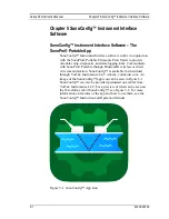
are using the SonoConnect™ breakout box, there are two connections that must
be correct. The first is a female 25-pin DSUB connector on the SonoPro®
handheld unit. The second is a female 25-pin DSUB connector on the
SonoConnect™ breakout box.
a.
Verify that the 25 pin DSUB I/O cable is properly connected to the
Summary of Contents for SonoPro S34 Series
Page 34: ...Series S34 Instruction Manual Chapter 3 Operation 3 5 M 000 00030 Output Menu...
Page 69: ...Series S34 Instruction Manual Appendix A Specifications A 2 M 000 00030...
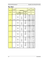
Page 73: ...Series S34 Instruction Manual Appendix C Sound Speed and Pipe Data C 2 M 000 00030 Pipe Chart...
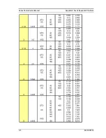
Page 74: ...Series S34 Instruction Manual Appendix C Sound Speed and Pipe Data C 3 M 000 00030...
Page 75: ...Series S34 Instruction Manual Appendix C Sound Speed and Pipe Data C 4 M 000 00030...
Page 76: ...Series S34 Instruction Manual Appendix C Sound Speed and Pipe Data C 5 M 000 00030...
Page 77: ...Series S34 Instruction Manual Appendix C Sound Speed and Pipe Data C 6 M 000 00030...
Page 78: ...Series S34 Instruction Manual Appendix C Sound Speed and Pipe Data C 7 M 000 00030...
Page 79: ...Series S34 Instruction Manual Appendix C Sound Speed and Pipe Data C 8 M 000 00030...


