39
in operation), that the output switch (Q2) is turned «On» in 2nd place
or subsequently (after the «Paral. Mst. Volt» or «Paral. Mst. Vt.Rsv»).
It will become as «Reserved voltage slave», when it works as
«Voltage Master». In those systems with more than three equipment
in parallel, the hierarchy of «Reserved voltage slave» will be taken by
the highest address between the «Voltage slave».
• Make sure that the inverter voltage is same, e.g.: 230Vac
• Turn all output switches from panel «On».
• Turn the output switch (Q2) of each UPS «On».
The system will supply voltage at the output terminals of the
protection panel.
˙
If the system has outgoing distribution protections, switch them
«On».
˙
Start up the loads to be supplied in a progressive way. The
system is started up completely, and the loads are protected through
the UPS.
• With the system running (switches turned «On»), when
shutdown or start up the inverter through the keypad of any UPS that
belongs to it, all of them will be turned «Off» or «On». In both cases,
the UPSs still supply output voltage at «On» position through the
inverters and «Off» position through the static bypass.
6.2.2.1 Take into consideration about Master and Slave
• Bypass Master and Slave («Mst. Byp.», «Slv. Byp.», «Slv. By.Rsv»).
■
Master manages the status of its own static bypass switch
and the one of the Slave equipment.
■
Equipment that are not sharing the load by the inverters.
The cause can be any of the following:
– Output switch (Q2) turned «Off».
– Equipment output on bypass.
– Inverters are shutdown or in start up process.
• Voltage Master and Slave («Mst. Volt», «Slv. Volt», «Slv. Vt.Rsv»).
■
Master manages both the status of its own static bypass
switch and the inverter voltage, as well as the one of the
Slave equipment.
■
Equipment are sharing the load on inverter. Therefore:
– Output switches (Q2) are turned «On».
– Inverters are running and static switches are on inverter.
6.3 SHUTDOWN OF ONE EQUIPMENT FROM THE PARALLEL
SYSTEM
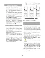
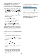
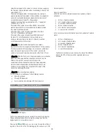
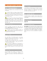
• Turn the output switch (Q2) of the UPS to shutdown «Off». In the
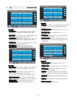
screen 0.0 from LCD panel will display:
6.4 START UP THE PREVIOUS UPS AGAIN
• Start up the inverter by means of the keypad from control panel.
• Turn the output switch (Q2) of the UPS «On».
6.5. COMPLETE SHUTDOWN OF THE UPS
˙
Shutdown the loads.
˙
If the system has outgoing distribution protections, switch them
«Off».
˙
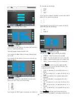
Shutdown the inverter. Please go to «CNTL» submenu (Screen 1.0),
and select «OFF». You will get Screen 1.2, asking you to shut down
the unit, by selecting
(YES) to shut down the inverter.
˙
Turn the output switch (Q2) to «Off» position.
˙
In standard units, set the input switch (Q1a) to «Off» position. In B
units, set the input switch (Q1a) and static bypass switch (Q4) to
«Off» position.
˙
Turn fuse holder switch from battery cabinet (Q8) and/or battery
fuse holder switch or switch from UPS (Q3), to «Off».
˙
Cut the power supply of the UPS and the bypass with the cut-off or
general switch of the header board. The system will be completely
deactivated.
˙
Electrical discharge hazard. If after shutdown of the equipment,
it is required to disconnect the separate battery pack/s, wait
several minutes (5 min. approx..), till the electronic capacitors have
been discharged.
˙
The equipment is completely shut down.
6.6.
EMERGENCY POWER OFF (EPO) OPEARTION
Emergency Power Off (EPO) is equivalent to a complete unit system
halt:
˙
All UPS converters are turned off (rectifier and inverter off).
˙
No output voltage is supplied to the loads.
See table below for operation:
E.P.O. function
Activation
(perform System Halt)
Return to
normal-mode.
Terminals (X50).
Normally closed
circuit by means
of the provided
cable bridge (it
allows an external
switch (EPO)).
Remote button or switch
has to be opened
permanently in terminal
strip (X50).
The equipment has to
be shut down and de-
energized completely
(turn off all switches),
wait till DC bus is
discharged (LCD has
to be turned off).
The equipment has to
be
started
up
according to section
“5.1.2.
Start
up
procedure”.
Table.4. Emergency Power Off (EPO) operation
Emergency shutdown function (EPO) can only be activated through
the terminal strip (X50). In a parallel system, it is not needed to make
additional connections than there is just only one equipment, because
through the communication BUS, any action over the button will
affect to the joint of the parallel system.
6.7. BYPASS MANUAL SWITCH (MAINTENANCE)
.
6.7.1. Principle of operation.
The integrated manual bypass of the UPS is a very useful element, but
Not connected
Screen 0.0

