18
i
o
(X36
0
)
(X32)
(X36
i
)
(X50)
(X31)
(X31)
(X36)
(X36)
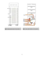
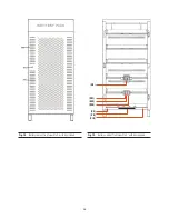
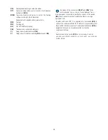
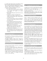
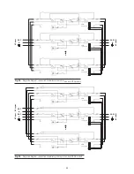
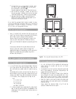
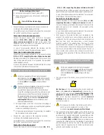
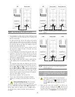
Fig. 18.
Connection of communications for models up to 60 kVA
(LV) / 120 kVA (HV).
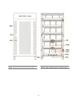
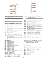
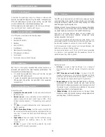
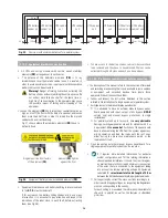
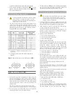
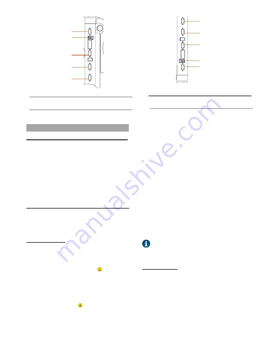
Fig. 19.
Connection of communications for models higher than
60 kVA (LV) / 120 kVA (HV).
4.1.2
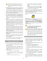
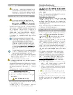
Legend corresponding to the equipment views.
Protection an
d maneuvering part
s (Q*) in the UPS cabinet:
(Q1a)
Input circuit breaker or switch according to the equipment
power rate, two or three poles respectively depending on
the mains typology.
(Q2)
Output switch.
(Q3)
Battery fuse holder switch with 3 fuses in models up to 20
kVA (LV) / 40 kVA (HV) or switch for B1 versions and higher
power rates models.
(Q4a)
Static bypass switch, two or three poles depending on
the mains typology (-B version only).
(Q5)
Manual bypass switch.
Protection and manoeuvring parts(Q*) in the battery cabinet:
(Q8)
Battery fuse holder switch of 3 fuses, for models up to 60
kVA (LV) / 120 kVA (HV).
Battery switch, in models higher than 60 kVA (LV) / 120 kVA
(HV).
Connection parts (X*):
(X1)
Terminal of input phase R.
(X2)
Terminal of input phase S.
(X3)
Terminal of input phase T.
(X4)
Terminal of input neutral N.
(X5)
Terminal (copper bar) of main earth
(
)
(X6)
Terminal of output phase U.
(X7)
Terminal of output phase V.
(X8)
Terminal of output phase W.
(X9)
Terminal of output neutral N.
(X10)
Terminal (copper rod) of earth bonding for load or loads
and/or battery cabinet
( )
.
(1)
(X11)
Battery positive terminal (+).
(1)
(X12)
Battery negative terminal (–).
(X14)
Terminal of static bypass phase R (-B version only).
(X15)
Terminal of static bypass phase S (-B version only).
(X16)
Terminal of static bypass phase T (-B version only).
(X17)
Terminal of static bypass neutral N (-B version only).
(1)
(X23)
Battery neutral N terminal (central tap).
(X31)
DB9
connector for COM RS-232 and RS-485 ports.
(X32)
DB9 connector for relay interface.
(X34)
Terminal strip of two terminals for temperature probe/floating
voltage. Equipment with separate battery cabinets only.
(X36
i
)
HDB15 female connector, parallel bus input. Only useful in
parallel systems co
nnection.
(X36
o
)
HDB15 male connector, parallel bus output. Only useful in
parallel systems connection
(X45)
Terminal strip of two terminals, auxiliary contact of output
switch. To be connected to its external homologous.
(X47)
Battery positive terminal (+) of the battery cabinet.
(X48)
Battery negative terminal (–) of the battery cabinet.
(X49)
Battery neutral terminal N of the battery cabinet (central
tap).
(X50)
External EPO terminals.
(X51)
Terminal strip of two terminals, auxiliary contact of manual
bypass switch. To be c
onnected to its external homologous.
(1)
:
Battery terminals
(X11)
,
(X12)
and
(X23
) available in
models > 20 kVA (LV) / > 40 kVA (HV) only, or in
equipment B1 type (extended back up time).
Other abbreviations:
(BC)
Communication BUS bundle between equipment, of 5 m.
length with HDB15 connectors in both ends.
(BF)
Rod to fix the connection wires of the equipment or battery
cabinet by means of wraps.
(BL)
Mechanical lock for manual bypass switch
(Q5)
.
(CL)
Front door lock.
(LL)
Key to lock and unlock
(CL)
.
(PB)
Levellers and fixing elements.
(PC)
Control panel.
(PF)
Front door.
(X50)
(X32)


