35
i
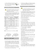
5.2.9.3. Terminal strip, battery temperature probe (X34).
For batteries in a separate cabinet only.
• As the battery manufacturer recommends a variable floating
voltage depending on the ambient temperature.
The control of this feature will be done through the
measurement of the temperature by means of a probe, located
inside the cabinet itself when batteries and equipment are
fitted in the same enclosure.
For those cases that batteries are supplied in a separate cabinet
out from the own UPS (
models >20 kVA (LV) / >40 kVA (HV),
t
here will be a terminal strip of two pins
(X34)
, that allows
bringing the probe located at the end of a two wires bundle with
4.5 m., till inside the battery cabinet.
The connection of the two wires from the cable bundle to the
terminal strip
(X34)
does not have polarity.
• Also via this probe the ambient temperature inside the battery
cabinet can be visualized in the control panel with LCD.
• The bundle with the probe will always be supplied already
connected to the terminal strip
(X34)
, so it is only necessary to
cut the clamp that keep it rolled, to take it out from the UPS
cabinet and enter it into the battery cabinet, in both cases,
through the foreseen cable bushing
(PR)
.
5.2.10. Connection of parallel BUS (X36
i
) and (X36
o
).
• This section is only useful for parallel systems.
• For the correct operation of the parallel functions and operating,
any unit connected in parallel are continuously communicated
among them. It is achieved by means of the called
communication line or BUS.
• Any operation of this section, regarding parallel systems, has to
be done by authorized staff of our firm.
• Once the power connections of the UPSs of the parallel systems
are done, it is needed to make the ones related to the control
or communication BUS. To do it, connect them in a sequential
way, two lines of the communication BUS between a unit and
its adjacent.
• Tog
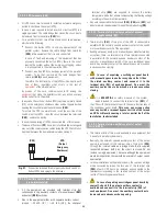
ether with each UPS of a parallel system, it is supplied a 15
wires bundle with HDB15 connectors at both ends, one male
and the other one female, with a length of 5 m. Therefore, there
will be as many communication BUS bundles
(BC)
, as quantity
of equipment to parallel have the system.
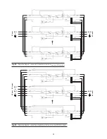
See Fig. 6 to 14 for COM
port physical layout.
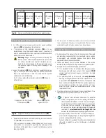
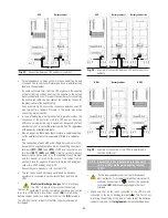
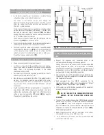
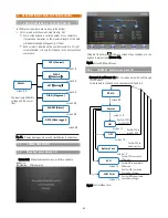
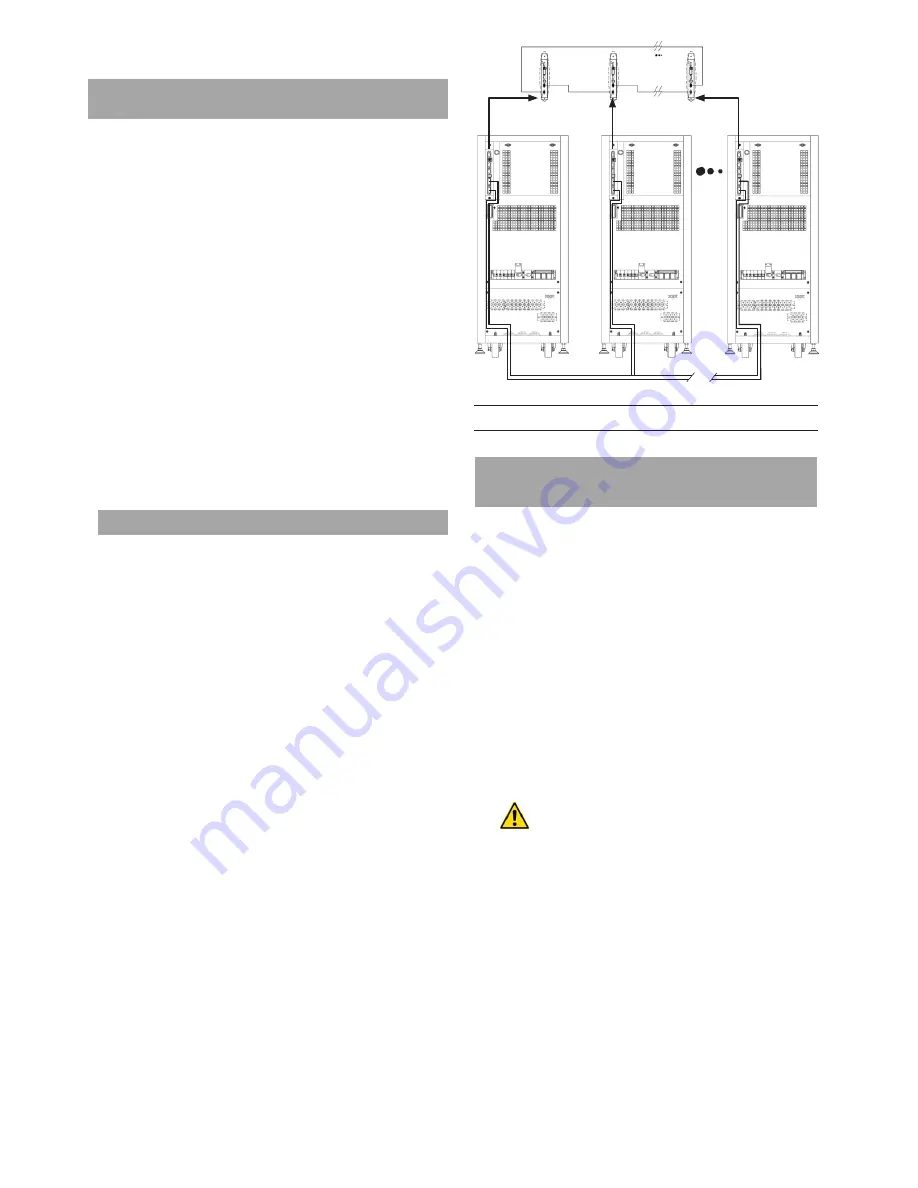
Fig. 32.
Connection of the communication BUS.
5.2.10.1. Connection of the communication or BUS bundle
(BC).
.
•
Respect th
e sequence and connection order of the
communication BUS among correlative equipment.
Although the order of the connections of communication BUS
among equipment are made, is not important, on condition
that the communication loop is completed or closed properly, it
is advisable to carry out the connections with the immediately
next equipment in order simplify the connection.
• The connection limit of the installation, will be determined by
the quantity of available equipment to parallel and in any case
till a maximum of four units.
• Each equipment has two HDB15 connectors for the
communications among them, one male labelled as “Output”
(X36
i
)
and another one female as “Input”
(X36
°
)
.
• In the same way, all the bundles supplied with the equipment,
are equal in connections and length.
DO NOT MODIFY THE COMMUNICATION BUS
BUNDLE, OR THE CONNECTORS UNDER ANY
CONCEPT
.
• Take one of the bundl
es and insert the HDB15 female connector
located in one of its ends, into the male connector labelled as
“Output”
(X36
°
o
)
, in any of the equipment of the system and
insert the HDB15 male connector located in the opposite end of
the bundle into the female connector labelled as “Input”
(X36
)
Of the adjoining equipment.
• Repeat the previous step with each equipment of the system,
till closing the communication BUS loop or ring.
• As an example, Fig. 32 shows, how the communication BUS
connections have to be done.

