37
6. OPERATING.
• During the description of this section, it is detailed the procedure
to follow to get the different functionalities, considering a system
of
«n»
equipment
connected in parallel.
If in your case, it is available
only one
UPS from
UPS
, series,
proceed in the same order, but simplifying the operating for a
single
unit.
•
As it has been stated before, it is advisable to have an
external manual bypass panel board equipped with
input, output, static bypass (
UPS B
version only) and
manual bypass protections, in single installations.
For parallel systems up to two units, it
is very advisable
having a switchgear panel board and for systems with
3 or 4
equipment
,
it is essential
. Switches of the panel board
have to allow isolating a UPS from the system against any
wrong
operation
and feeding the loads with the rest ones,
either during the preventive maintenance period or the
self-reparation
.
Therefore it has been considered appropriate and naturally,
to contemplate in the instructions of the equipment, the
operation
of a system with
«n»
equipment connected in
parallel with their respective external manual bypass
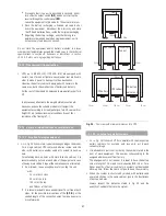
panel board as it is shown in the
«
Recommended
installation
»
documentation included in the CD.
This panel board allows isolating each equipment individually in
case of fault and removing it without any difficulty for its
reparation or replacement. Also, the included manual bypass
switch makes
it
easier
to do
the preventive maintenance tasks
or intervention over the complete system, supplying the
voltage to the loads directly from mains, on the
«
bypass
»
mode
operation
, mean- while the input voltage is available.
In those installations without the external manual bypass panel
board, omit the actions and steps that involve the maneuvering
of their switches.
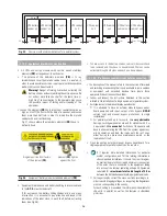
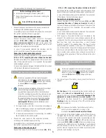
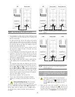
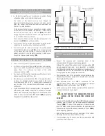
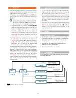
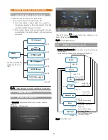
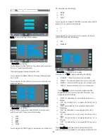
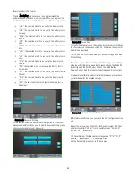
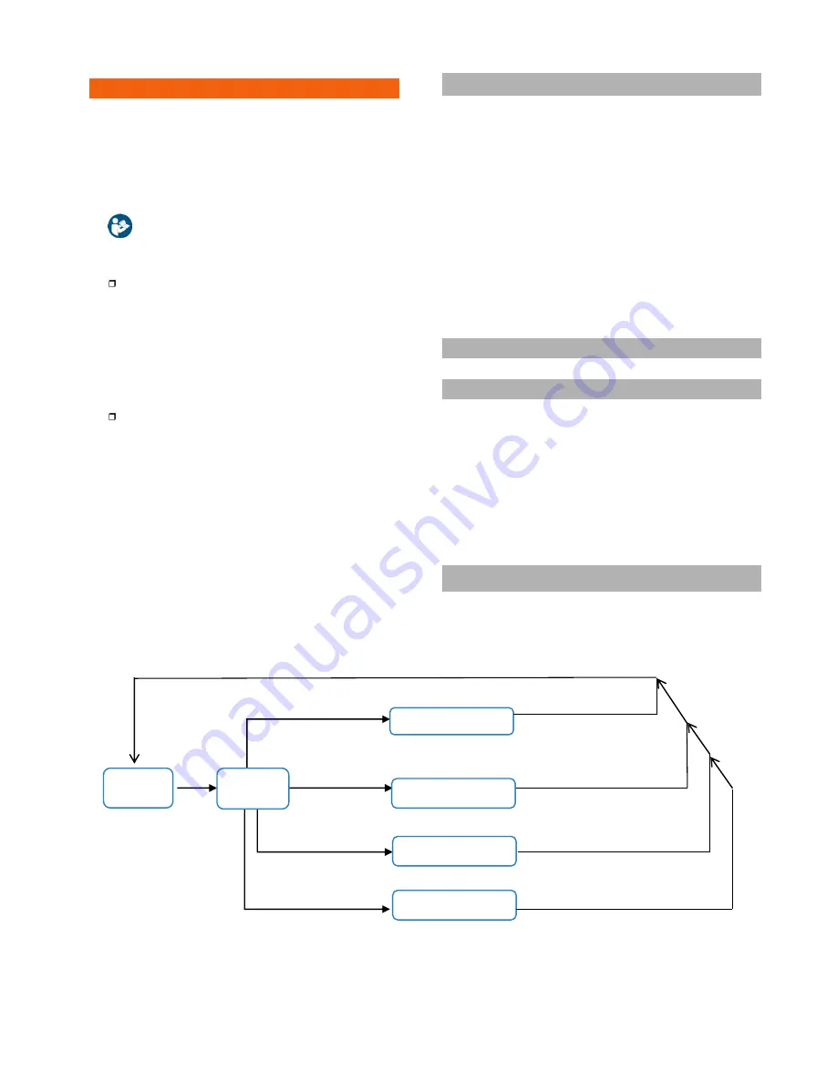
Fig.33. Procedure start-up / shutdown.
6.1. PRELIMINARY CONSIDERATIONS.
• It is very important to always operate in the established order
in the described instructions in the next sections, by respecting
the sequence of the switches in relation to its function.
So, i.e. in parallel system based on four
equipment
, when it is
stated to turn on the
«
Input
»
mechanisms, the order of turning
on them will not matter, but any other switch with different
function as it could be
«
Output
»
switch will not be turned on,
till is stated.
• Unlike other UPS structures, where the
«
Master
»
and
«
Slave
»
equipment
are preset strictly from factory, conditioning the
order of
start-up
and shutdown, the new
UPS
series is
managed by a more flexible hierarchy according to the
operating mode that it is.
6.2.
START UP
6.2.1. Control before start up
˙
Carefully make sure that all the connections have been made
correctly and are sufficiently tight, respecting the labelling of the
device and the instructions of chapter «4.- Installation and
wiring of the unit».
˙
Check that the UPS switches and the batteries cabinet or
cabinets are turned off (position «Off»).
˙
Be sure that all the loads are turned «Off».
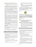
6.2.2. Start up procedure
It is very important to operate in the established order, considering
the following instructions.
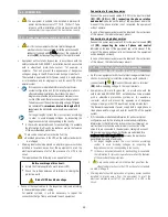
ECO
ON/OFF
BATTERY TEST
CNTL
(Control)
Main
FAST CHG
screen 1.5
screen 1.4
screen 1.1
screen 1.3
screen 1.0
screen 0.0
screen 1.2
Confirm YES to do
Battery Test
If UPS is OFF, confirm
YES to turn ON UPS
If UPS is ON, Confirm YES
to turn OFF UPS.
Confirm YES to activate
ECO mode
Confirm YES to activate
Fast Battery Charger

