50
sizing the equipment in the system, in order to continue supplying
the maximum permissible load without overloading it. Usually, this
value is fixed to “1”.
The alarm is displayed when the load exceeds the maximum
permissible load by N equipment. In this condition, the equipment
will not be overloaded individually, meanwhile the load doesn’t
exceed the maximum load of N+M equipment.
Example: Assuming that a parallel system of 2+1 equipment
of 20kVA (N=2, M=1).
If the load of the system is lower than 40kVA. Any overload
alarm is displayed (if it is not exceeded the individual overload
for phase for each equipment).
If the load of the system is higher than 40kVA. The alarm
74 of Lost of Redundancy is displayed.
If the load of the system is higher than 60kVA. Besides of
the alarm 74 Lost of Redundancy, there will also be, at
minimum, (among others), the alarm 2 of Inverter overload
in all the equipment of the system.
˙
Alarm 75: This alarm can be displayed for two reasons:
Input contactor from the equipment faults (it doesn’t close properly).
It is shown when the DC bus voltage, it is not kept at certain level
when closing such input contactor. The system can retry the
contactor test several times (see description of the Alarm 47 too).
˙
Alarm 76: After the first error in the parallel system communication,
when one of the equipment has already been chosen as a Fix
Master in the system, a second error or break in the
communications has been detected by the Slaves equipment,
which will be blocked permanently (Rectifier and Inverter are
shutdown, output voltage is not supplied to the output of the
system), by displaying this alarm.
˙
Alarm 77: Error in configuration memory
(*) DSP Internal Error can happen for the following reasons:
Watch Dog failure.
Wrong ADC measured.
Communication errors between DSP and processor.
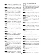
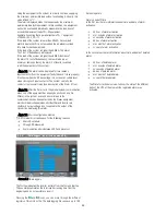
7.2.6. ‘‘Data Logger’’ level (screen menu 5.0).
˙
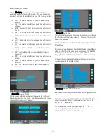
Screen 5.0 «Data logger»
The first line indicates the inverter runtime from the first unit start-up.
This counter accumulates the total inverter running time from the
beginning and it’s not possible to reset it.
Pressing the
and
icons, you can move through the different
registers of this historic file. The data logging file can save up to 100
historic registers.
Alarm on and off time
In the first row there is information about time and date of alarm
activation:
hh: hour of alarm activation
mm: minutes of alarm activation
ss: seconds of alarm activation
dd: day of alarm activation
mm: month of alarm activation
yy: year of alarm activation
In the second row there is information about time and date of deleted
alarm.
hh: hour of deleted alarm
mm: minutes of deleted alarm
ss: seconds of deleted alarm
dd: day of deleted alarm
mm: month of deleted alarm
yy: year of deleted alarm
The State for technical service, to know the state of the different
parts of the UPS at the moment the registered alarm was
activated.


