23
etc.). Whateve
r type of load to protect is, the equipment is ready to
assure the quality and uninterruptible electrical power supply.
The use of the transformerless technology allows a significant
reduction of weight and volume in the equipment, by improving
important co-efficiency a lot like the power/footprint ratio.
• Basically its operating is the following:
The rectifier, an IGBT three phase rectifier, converts the
AC voltage in DC by draining a sinewave current (THDi
<2%), charging the batteries with constant
current/voltage.
Batteries supply the energy required by the inverter in case
of mains fault.
The inverter is in charge of converting the DC bus
voltagein to AC by providing an alternating sinewave output,
stabilizing voltage and frequency, ready to supply the loads
connected at the output.
The basic structure of double conversion is complemented
with two new functional stages, static bypass switch and
manual bypass switch.
The static bypass switch connects the output load with
bypass line directly in special conditions like overload or
over temperature and it is reconnected to inverter again,
once the normal conditions are restored.
UPS B
version has two separate lines for the rectifier
and bypass stages increasing in the safety of the
installation, because it allows the use of a second line
(generator set, other company, etc...).
The manual bypass switch isolates the UPS from mains and
loads connected at the output, so the maintenance tasks
can be done inside the UPS without interrupting the supply
to the loads.
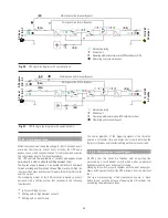
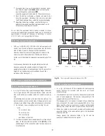
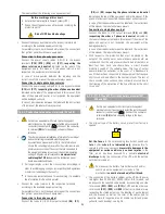
4.4.1. Normal operating (
).
With mains present, the rectifier converts the AC input voltage into
DC, by boosting the DC voltage to an optimal level to feed the
inv
erter and battery charger.
The inverter is in charge of converting the DC bus voltage into AC
by providing
an alternating sinewave output, it stabilizes the
voltage and frequency, ready to supply the loads connected at the
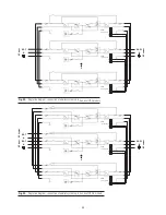
output (Fig. 20 and 21).
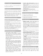
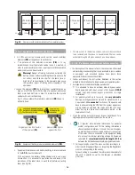
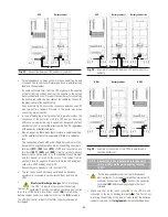
4.4.2. Mains fault operating (
).
In case of mains fault or blackout, the battery set supplies the
needed energy to feed the inverter.
The inverter stil
l operates normally, without noticing the lack of
mains and the back-up time depends on the capacity of the battery
set only (Fig. 20 and 21).
When the battery voltage reaches the low voltage, the control
blocks the output in order to protect the batteries from being deep
discharge. When mains is restored and after the first analysis, the
UPS goes back to operate as it is described in the previous
section «4.4.1. Normal operating».
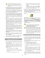
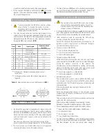
4.4.3. Operating with non-active inverter (
).
The inverter is non-active due to alarm conditions like overloads,
over temperatures, etc... In this case the rectifier is still charging the
batteries in order to keep their optimal charge status.
The inverter is a
lso non-active if the start-up has not been done
through the keypad of the control.
In both cases, the output voltage of the UPS comes from the
emergency bypass line through the static bypass switch (Fig. 20 and
21) in the condition that t
he EPO is inactive.
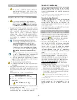
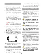
4.4.4. Manual bypass operating (
).
When it is required to make any maintenance service to the
equipment, it can be disconnected from mains without breaking
the power supply of the sys
tem and affecting the critical load.
The UPS can only be intervened by technical or maintenance staff,
by means of the manual bypass switch (respect the corresponding
operative instructions stated later on)
.
4.4.5. Smart Eco-mode operating.
For those applications with lower requirements, the smart and
efficient function «Smart Eco-mode», meanwhile the power
supply is available, allow the equipment to feed the loads directly
from mains through the solid static bypass state («Off Line» mode).
In case of mains fault, the system will automatically shift to normal
operating mode («On Line») and will supply the loads through the
inverter with the energy of the batteries. The «Smart Eco-mode»
operating mode improve the efficiencies between 4 and 4.5 %
highest than «On Line» normal mode, so it is close to 100 %.
The «Smart Eco-mode» operation does not ensure a perfect
stabilization in frequency, voltage or sinewave sh
ape (distortion)
as in «On Line» normal mode, because the figures of these
parameters depend on the static bypass line and preset activation
ranges completely.
The detection of these parameters can take up to 3 ms, so it is
recommended to assess the advisability of using this operating
mode, de
pending on the level of protection required by the loads.
This operating mode is disabled from factory and the end/user can
activate it if needed, according to section 7.2.2. and Fig. 35.
This operating mode is disabled from parameters and the end/user
can activate it if needed
4.4.6. Frequency converter operating.
.
This UPS
can be set from factory as frequency converters, whether
they has
batteries or not, being able to operate from 50 to 60 Hz or
vice versa.
The equipment is set as frequency converters, so the static bypass
and manual bypass are not available.
So, those functions, measurements, alarm messages, parameter
settings, as well as maneuvering of the relate
d switches will not be
operative and they will not be taken into account.


