32
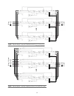
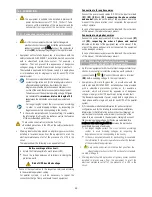
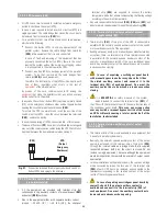
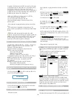
UPS
Battery cabinet
UPS
Battery cabinet 1
Battery cabinet «N»
+ N –
+ N –
+ N –
+ N –
+ N –
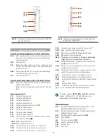
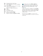
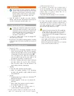
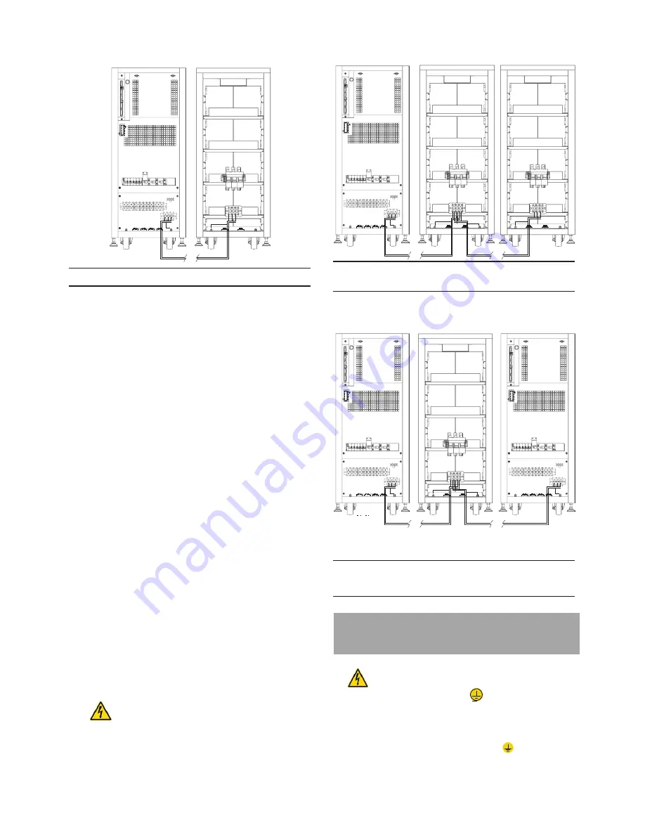
Fig. 27.
Connection between UPS and battery cabinet.
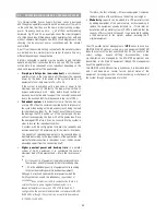
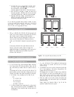
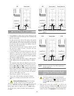
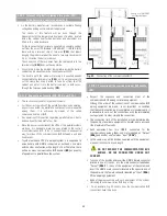
Fig. 28.
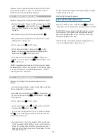
Example of connection between UPS and two battery
cabinets.
• For extended back up times with more than one battery module
or cabinet, the connection will always be done in parallel among
them and the equipment.
So, cable with black color, from the UPS negative to the negative
of the first battery cabinet and from this negative to the second
battery cabinet and so on. Proceed in the same way, for connecting
the positive red cable, the blue cable of the middle tap (N) and for
the green-yellow of the earth bonding.
As an example Fig. 28 shows the connection between one UPS
and two battery cabinets. Proceed in the same way when
connecting more modules.
• In case of belonging or being connected to parallel system, the
connection of the batteries with the UPS don not have any
difference as regards to a single equipment, because by default,
each battery set is connec
ted directly with its UPS, regardless
of the quantity of battery cabinets.
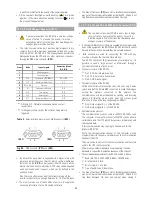
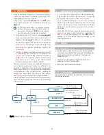
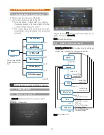
UPS 1
+ N –
Battery cabinet
+ N –
UPS 2
+ N –
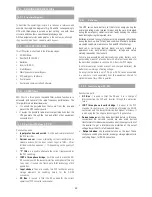
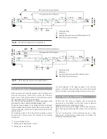
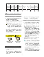
• Also, as an option, there is another structure, a common battery
set for parallel system of two equipment fitted in a cabinet or
rack.
The connection of each UPS with the ba
ttery cabinet will be
done with the supplied cable bundle, by connecting one side to
terminals
(X11)
,
(X23)
and
(X12)
of UPS and the other one to
terminals
(X47)
,
(X49)
and
(X48)
of battery module, always
respecting the stated polarity on the labelling of each element
and this manual, as well as the color of the cables (red for
positive, black for negative, blue for middle tap (N) and green-
yellow for earth bonding), see Fig. 29.
Repeat the same procedure with the other UPS.
• This set can be extended in back up time and be based on
several units connected in parallel among them and the own
UPSs.
•
Electrical discharge danger
. If after starting up
the
UPS, it is required to disconnect the battery
cabinet, the
equipment has to be completely shutdown (see section
6.5). Turn off the battery fuse holder switch
(Q8)
located in the
battery cabinet and/or fuse holder switch or switch
(Q3)
located in
the UPS. Wait 5 min. at least till the filter capacitors have been
discharged.
Fig. 29.
Example of connection of two UPSs in parallel and a
common battery set.
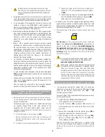
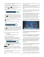
5.2.5. Connection to the input main protecting earth
terminal (X5) and the earth bonding terminal
(X10) .
.
•
As this is an equipment with class I protection against
electrical shocks, it is essential to install the protection
earth
conductor (connect earth
( )
). Connect this conductor
to terminal
(X5)
, before supplying voltage to the input
terminals.
• Make sure that all the loads connected to the UPS are only
connected to the earth bonding terminal
( )
. The fact of not
restricting the earthing of the load or loads and/or the batteries
cabinet or cabinets to this
single point
will create backfeed loops

