


5.12 DC Brake with External Zero Speed
Sensor
For loads which may vary between braking cycles, there
are benefits in using an external zero-speed sensor to
interface with the MCD 500 for brake shut-off. This control
method ensures that the MCD 500 braking will always shut
off when the motor has reached a standstill, thus avoiding
unnecessary motor heating.
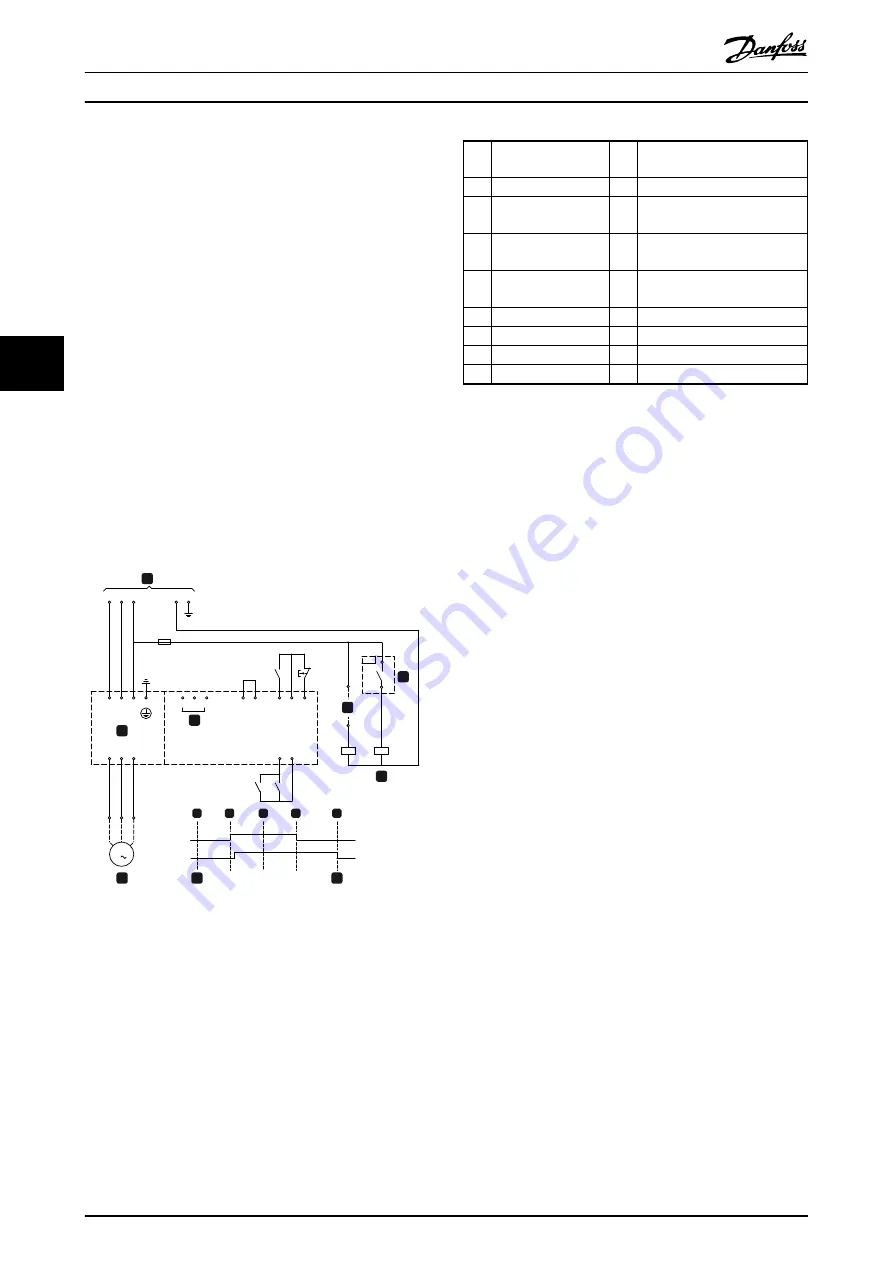
The following schematic diagram shows how you can use
a zero-speed sensor with the MCD 500 to turn the brake
function off at motor standstill. The zero-speed sensor (-
A2) is often referred to as an under-speed detector. Its
internal contact is open at zero-speed and closed at any
speed above zero-speed. Once the motor has reached a
standstill, the MCD 500 will go into Emergency Stop mode
and remain in this state until the next start command is
given (i.e. next application of –KA1).
The MCD 500 must be operated in remote mode and
3-3
Input A Function
must be set to emergency stop.
-F1
L3
L2
L1
N
E
-KA1
L1
L2
L3
E
T1
T2
T3
A5
A4
A6
15
16
17
18
25
11
16
-KA1
-KA2
-KA1
-KA2
T3
T2
T1
M
3
-KA2
-KA1
-A2
177HA6
19.
10
4
1
3
2
5
A
B
C
D
E
6
7
5
8
Illustration 5.14
1
Soft starter
4
Emergency stop mode (shown
on starter display)
2
Control voltage
A
Off (ready)
15,
16
Start
B
Start
17,
18
Stop
C
Run
25,
18
Reset
D
Stop
2
Motor
E
Zero speed
3
Three-phase supply
5
Start signal (2, 3, or 4-wire)
6
Zero speed detect
7
Zero speed sensor
Table 5.15
For details on configuring DC Brake, see
.
NOTE
When using DC brake, the mains supply must be
connected to the soft starter (input terminals L1, L2, L3) in
positive phase sequence and
2-1 Phase Sequence
must be
set to
Positive only
.
5.13 Soft Braking
For high inertia loads the MCD 500 can be configured for
soft braking.
In this application the MCD 500 is employed with forward
run and braking contactors. When MCD 500 receives a
start signal (button S1), it closes the forward run contactor
(KM1) and controls the motor according to the
programmed primary motor settings.
When the MCD 500 receives a stop signal (button S2), it
opens the forward run contactor (KM1) and closes the
braking contactor (KM2) after a delay of approximately 2-3
seconds (KT1). KA3 is also closed to activate the secondary
motor settings, which should be user programmed for the
desired stopping performance characteristics.
When motor speed approaches zero, the external shaft
rotation sensor (A2) stops the soft starter and opens the
braking contactor (KM2).
Some shaft rotation sensors perform a self-test upon
power-up and momentarily close the output relay. In these
cases, also install a delay timer (KT3).
Application Examples
MCD 500 Operating Instruction
42
MG17K402 - VLT
®
is a registered Danfoss trademark
5
5